Freya Yang
+86 18318948097
+852 62667476
10.25 Inch Panoramic Cockpit Information TFT LCD Module
Model P/N
Size
Resolution
Brightness
Viewing Angle
Connector Type
Operating Temp
Overall(mm)
huisoar
HS103002S0
Brand
Panel Size (inch)
Model P/N
Resolution
Brightness (nits)
Viewing Angle
Contrast Ratio
Response Time
Overall (mm)
Active Area (mm)
Refresh Rate
Display Colors
Panel Type
Connector Type
Operating Temp
Touchscreen Type
Storage Temp
Work Mode
Control Type
Operating Environment
Designed For
10.25 Inch Panoramic Cockpit Information TFT LCD Module
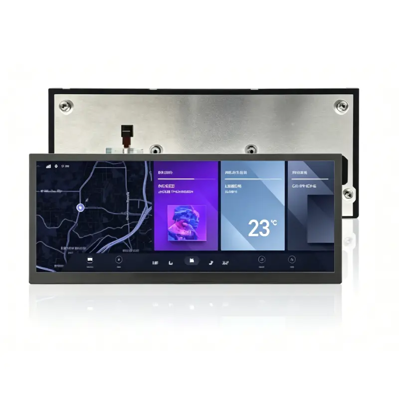
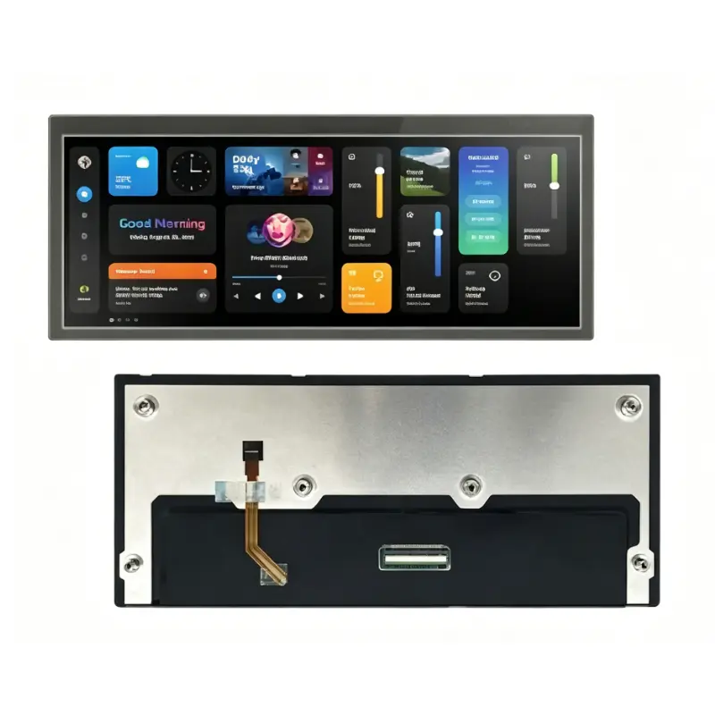
The Panoramic Cockpit Information TFT LCD Module combines a native 1920 × 720 IPS panel, 1000 cd/m² luminance and 40-pin LVDS integration for vehicle HMI.
Product Summary
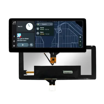
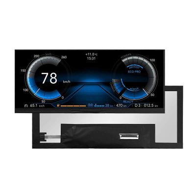
The Panoramic Cockpit Information TFT LCD Module provides a wide, low-profile interface for digital instrument clusters, navigation panels and vehicle information zones. Its 10.25-inch format is designed for layouts that distribute driving data, route guidance, status indicators and alerts across a continuous horizontal screen.
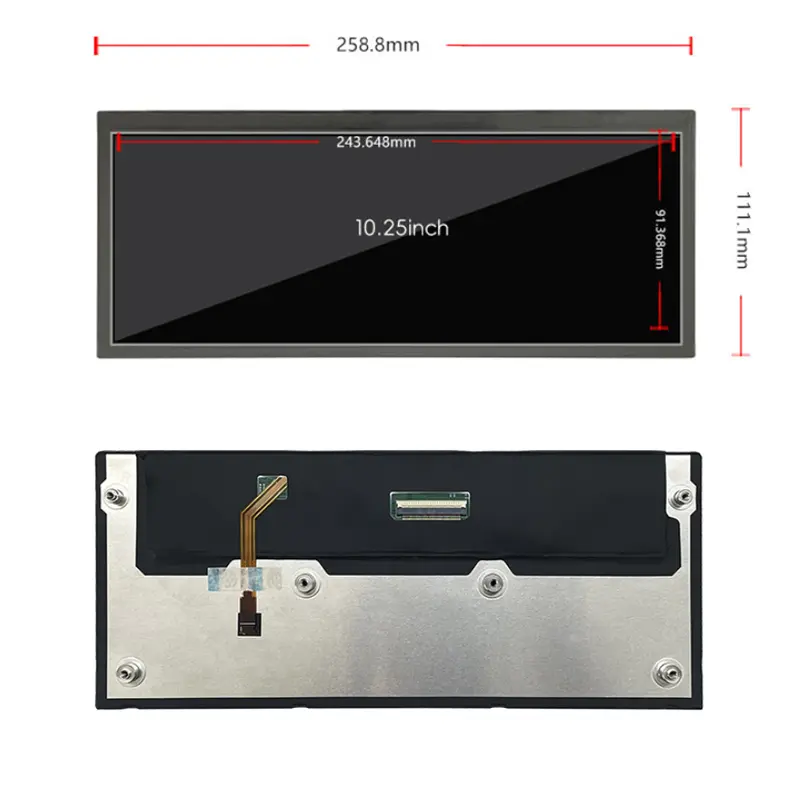
The module combines an IPS panel, 1000 cd/m² typical luminance, an 800:1 typical contrast ratio and confirmed 80/80/80/80 viewing angles. Its active area measures 243.648 × 91.368 mm within a 258.8 × 111.1 × 7.55 mm overall envelope. The native interface is 40-pin LVDS, and the standard configuration is non-touch.
Key Specifications
| Parameter | Value |
|---|---|
| Display size | 10.25 inch |
| Resolution | 1920 × 720 pixels |
| Format | Panoramic, approximately 8:3 |
| Panel type | IPS a-Si TFT-LCD |
| Luminance | 1000 cd/m² typical |
| Contrast ratio | 800:1 typical |
| Viewing angle | 80/80/80/80, L/R/U/D |
| Display colors | 262K |
| Pixel arrangement | RGB stripe |
| Interface | 40-pin LVDS |
| Active area | 243.648 × 91.368 mm |
| Overall size | 258.8 × 111.1 × 7.55 mm |
| Backlight | WLED |
| Touch | Non-touch |
| Operating temperature | −20°C to +70°C |
| Storage temperature | −30°C to +80°C |
Native 1920 × 720 Panoramic Interface Design
Cockpit Information and Navigation Zones
The 1920 × 720 canvas supports multiple information zones across one continuous display. A cockpit interface can allocate space for:
- vehicle speed and operating data
- warning indicators
- navigation guidance
- route maps
- media or communication status
- energy or fuel information
- climate status
- equipment modes
- driver notifications
The panoramic format provides more horizontal content space than a conventional 16:9 panel of similar height. This can help product teams create a visually unified dashboard rather than using several separate display areas.
Native-Raster Software Preparation
The native 1920 × 720 raster should be used to preserve panoramic cockpit geometry and text detail.
Before approving the interface, validate:
- native display timing
- aspect-ratio handling
- font scaling
- icon dimensions
- warning-message position
- navigation-map scaling
- content-safe margins
- boot-screen dimensions
- camera-image handling
- night and day UI themes
A graphics source configured only for 1920 × 1080 may crop, stretch or letterbox the panoramic output.
Optical Performance for Vehicle Cabins
1000 cd/m² Luminance Boundary
The panel is specified at 1000 cd/m² typical luminance. This can support bright vehicle cabins and other high-ambient-light installations more effectively than standard indoor-luminance panels.
A 1000 cd/m² panel does not by itself establish finished-system sunlight readability behind front glass.
Finished-system performance also depends on:
- cover-lens transmission
- surface reflection
- air-gap construction
- optical bonding
- installation angle
- dashboard geometry
- direct daylight exposure
- thermal conditions
Representative samples should be tested with the intended cover lens and enclosure.
IPS Viewing and Contrast
The panel provides 80/80/80/80 viewing angles in left, right, upper and lower directions. This supports driver and passenger viewing positions that are not centered directly in front of the display.
The 800:1 typical contrast ratio supports visual separation between background graphics, navigation elements, instrument values and warnings. The module displays 262K colors, so the graphics controller and UI assets should be prepared for the confirmed color capability rather than assuming a higher bit-depth path.
40-Pin LVDS Host Integration
Timing, Mapping and Pinout Qualification
A 40-pin LVDS connector does not guarantee timing, voltage, channel, bit-depth or pin compatibility with another panel.
Before fabricating a cable or applying power, confirm:
- native 1920 × 720 timing
- LVDS channel count
- bit configuration
- signal mapping
- signal voltage
- complete 40-pin assignment
- connector pitch
- contact side
- connector orientation
- panel power
- backlight voltage and current
- dimming and enable signals
- cable length and routing
Similar 10.25-inch 1920 × 720 displays are currently sold with different connector counts and interface definitions, so diagonal size and resolution alone do not establish interchangeability.
Non-LVDS Sources Require Conversion
HDMI, DisplayPort, eDP, MIPI DSI and USB video cannot connect directly unless a controller converts the source into the required LVDS timing.
The conversion solution should be checked for:
- accepted input modes
- native 1920 × 720 output
- scaling behavior
- LVDS channel and bit mapping
- color-depth support
- panel and backlight power
- startup behavior
- controller-board dimensions
- thermal performance
- connector clearance
Support for 1920 horizontal pixels does not prove support for the complete panoramic timing.
Panoramic Cockpit Information TFT LCD Module Mechanics
Active Area and Front Opening
The active image area is 243.648 × 91.368 mm. This value should guide:
- visible bezel opening
- cover-lens window
- printed black mask
- panel alignment
- UI-safe margins
- navigation-map position
- warning-indicator placement
Critical driving information should remain within the approved visible opening after bezel overlap and assembly tolerances are applied.
Outline and Rear Clearance
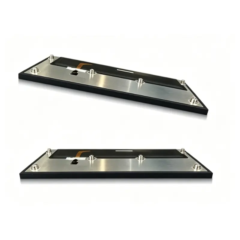
The module envelope is 258.8 × 111.1 × 7.55 mm.
Mechanical review should include:
- complete panel outline
- active-area position
- rear clearance
- connector access
- cable exit
- cable bend radius
- mounting support
- cover-lens overlap
- thermal airflow
- service access
The approximate 10.25-inch diagonal or rounded dimensions should not control enclosure tooling when precise mechanical values are available.
Temperature and Environmental Qualification
The module is specified for operation from −20°C to +70°C and storage from −30°C to +80°C.
These limits support evaluation in vehicle cabins and selected embedded equipment, but they do not independently establish automotive certification or suitability for every installation.
System-level qualification should consider:
- cold startup
- hot-cabin operation
- backlight performance across temperature
- enclosure heat
- controller temperature
- condensation
- cable flexibility
- vibration and shock requirements
- repeated thermal cycling
Sample testing should use the final optical, electrical and mechanical configuration.
Non-Touch HMI Architecture
The standard module is non-touch. This suits applications where interaction is provided through:
- steering-wheel controls
- physical dashboard buttons
- rotary controllers
- touchpads
- external switches
- remote system controls
- a separately developed touch assembly
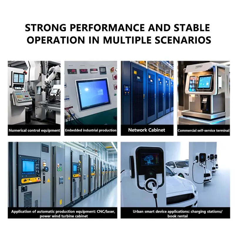
Potential applications include:
- digital instrument clusters
- navigation displays
- cockpit information panels
- vehicle status interfaces
- transport-equipment HMIs
- panoramic industrial control panels
- selected 3D-printer interfaces
Vehicle use must be validated at the complete-system level.
Custom Integration Options
Project review may include:
- LVDS controller matching
- custom 40-pin cable
- timing and mapping verification
- brightness evaluation
- cover-lens sizing
- anti-glare or anti-reflection treatment
- optical bonding
- enclosure adaptation
- mounting support
- logo or graphic printing
- optional touch development
- packaging and labeling
Custom configurations are generally reviewed from 500 pieces, subject to tooling requirements, material availability and the requested specification. Sample and standard-module quantities are confirmed separately.
For a Panoramic Cockpit Information TFT LCD Module project, customization should begin after the interface definition and mechanical drawing have been approved.
Procurement Checklist
Before requesting samples or production approval, submit or confirm:
- native 1920 × 720 timing
- LVDS channel count
- LVDS bit configuration
- complete 40-pin assignment
- signal voltage
- panel power
- backlight voltage and current
- connector pitch and orientation
- controller-board model
- approved module drawing
- 243.648 × 91.368 mm active-area position
- 258.8 × 111.1 × 7.55 mm enclosure fit
- front-glass stack
- 1000 cd/m² lighting target
- operating-temperature requirements
- non-touch or optional-touch architecture
- sample quantity
- annual demand
- production schedule
Sample approval should precede controller release, cable manufacture, cover-lens tooling and enclosure production.
FAQ
About 10.25 Inch Panoramic Cockpit Information TFT LCD Module
What must be checked before connecting a 40-pin LVDS host?
How should a 1920 × 720 cockpit interface be prepared?
Does 1000 cd/m² guarantee sunlight readability?
Which dimensions should control enclosure release?
When should the non-touch configuration be selected?
Freya Yang
+86 18318948097