
~
~
~
~
~
~
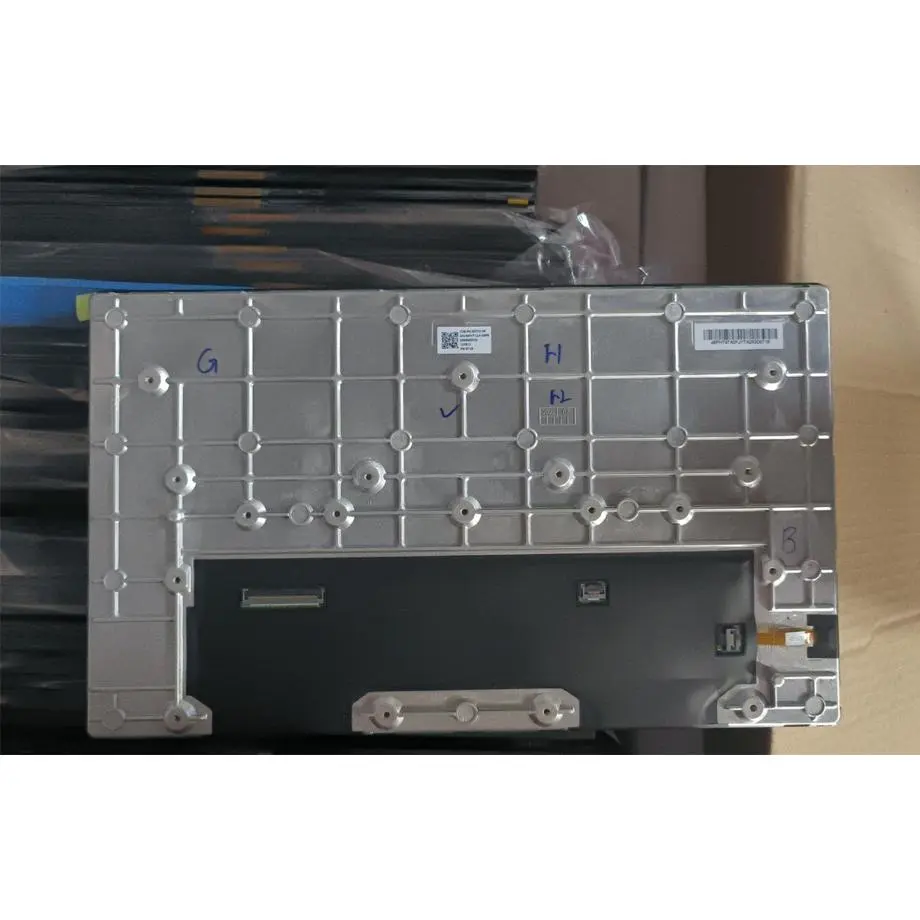
AS146FHT-L14-68P2 800-Nit 10G LVDS Touch Assembly 14.6″ BOE
Model P/N
Size
Resolution
Brightness
Viewing Angle
Connector Type
Operating Temp
Overall(mm)
boe
AS146FHT-L14-68P2
Brand
Panel Size (inch)
Model P/N
Resolution
Brightness (nits)
Viewing Angle
Contrast Ratio
Response Time
Overall (mm)
Active Area (mm)
Refresh Rate
Display Colors
Panel Type
Connector Type
Surface Treatment
Operating Temp
Touchscreen Type
Storage Temp
Work Mode
Pixel Format
Input Voltage (V)
Touch Interface
Vibration Resistance
Designed For
Product Details
Product Overview
The AS146FHT-L14-68P2 800-Nit 10G LVDS Touch Assembly is a 14.6-inch BOE LTPS TFT-LCD assembly for demanding display integration where brightness, environmental range and integrated touch all matter. It uses a native 1920(RGB)×1080 FHD image over a 323.136 × 181.764 mm active area, with a documented 339.72 × 203.97 mm overall width and height. The panel is specified for 800 cd/m² typical luminance, 1000:1 typical contrast, 85/85/85/85 typical viewing at CR≥10 and 16.7 million colors in ADS normally-black transmissive mode.
The assembly combines two-channel 8-bit LVDS on a 60-pin connector with In-Cell Touch using I²C, a 3.3 V typical panel input and an 11S4P WLED backlight without its driver. It is specified for -40 to 85 °C operation, -40 to 90 °C storage and 10.0G (98 m/s²) vibration. Those values support rugged-industry, automotive-display and outdoor-high-brightness evaluation, but they do not by themselves establish an automotive-grade certification, functional-safety rating, EMC class or any other program-specific approval.
Three Core Buyer Value Propositions
800-nit panel luminance creates a stronger starting point for bright-environment HMI design
The 800 cd/m² typical luminance gives system designers more optical margin than a standard indoor panel when the target installation faces high ambient light. That is useful for vehicle displays, outdoor-facing terminals and rugged equipment, but finished-system readability still depends on the cover lens, reflections, optical stack, dimming range and ambient conditions. The brightness value should therefore be treated as a verified module-level parameter rather than a guarantee of sunlight readability.
Wide temperature and 10G vibration data provide concrete environmental screening limits
The documented -40 to 85 °C operating range, -40 to 90 °C storage range and 10.0G vibration figure give engineering teams measurable component-level boundaries for qualification planning. These values are stronger evidence than a generic “rugged” label, yet they are not a substitute for the target equipment’s required standard, test method, duration, axis, mounting condition or functional acceptance criteria. Program-level environmental compliance still has to be defined and verified separately.
In-cell I²C touch reduces front-stack separation between display and input
The touch function is integrated into the display assembly rather than being described as a separate overlay. The current product facts identify In-Cell Touch and I²C, which allows the host architecture to plan the touch-control path separately from LVDS video. Touch-point count, firmware protocol, interrupt behavior, glove performance, wet-touch performance and controller identity are not carried into the formal record unless model-specific evidence is available.
Key Specifications at a Glance
| Parameter | Specification |
|---|---|
| Manufacturer / model | BOE AS146FHT-L14-68P2 |
| Size / construction | 14.6 inch LTPS TFT-LCD, Assembly |
| Resolution | 1920(RGB)×1080 FHD, 16:9 |
| Active area | 323.136 × 181.764 mm |
| Overall width / height | 339.72 × 203.97 mm; thickness requires confirmation from the current mechanical drawing because secondary source entries conflict |
| Weight | 1.20 ± 0.02 kg |
| Brightness / contrast | 800 cd/m² typical / 1000:1 typical |
| Viewing / response | 85/85/85/85 typical at CR≥10 / 30 ms maximum Tr+Td |
| Display mode / color | ADS normally black transmissive / 16.7M colors |
| Surface | Anti-fingerprint + antiglare, hard coating 3H, antireflection |
| Native display interface | LVDS, 2 channels, 8-bit, 60-pin connector |
| Touch | In-Cell Touch, I²C |
| Panel input | 3.3 V typical |
| Backlight | 11S4P WLED, 40,000-hour reference, without driver |
| Refresh rate | 60 Hz |
| Environment | Operating -40 to 85 °C; storage -40 to 90 °C; vibration 10.0G (98 m/s²) |
| Designed for | Rugged Industry / Automotive Display / Outdoor High Brightness |
How should the two-channel LVDS path be qualified?
The AS146FHT-L14-68P2 800-Nit 10G LVDS Touch Assembly uses two-channel 8-bit LVDS through a 60-pin connector. Texas Instruments describes LVDS as a differential signaling technology whose real implementation depends on driver/receiver architecture, termination, data rate and signal-integrity conditions (TI Precision Labs: LVDS). For this BOE assembly, that means the exact panel timing, channel mapping, bit assignment, connector pinout and power sequence must come from model-specific documentation rather than from the LVDS label alone.
Connector fit is not an electrical compatibility test
A 60-pin cable that mates mechanically can still use a different LVDS map, power-pin arrangement or control-signal definition. Prototype qualification should use the released controller, cable and firmware at native 1920×1080 and 60 Hz. Include repeated power cycles, sleep/wake transitions, long-duration image operation and thermal testing. Record the approved cable and controller revision so a later replacement decision can reproduce the actual validated configuration.
What does In-Cell Touch over I²C require from the host?
The display video path and touch-control path should be treated as separate functions. LVDS carries pixel data, while the touch function uses I²C. NXP’s I²C-bus specification describes I²C as a bidirectional serial bus for communication between integrated devices (NXP I²C-bus specification). That general bus definition does not provide the touch register map, address, interrupt behavior or firmware protocol for this BOE assembly.
Touch behavior must be validated with the final mechanical stack
Coordinate mapping, startup behavior, interrupt handling and touch response should be tested with the released front assembly. The product facts establish In-Cell Touch and I²C, but they do not establish glove mode, wet-touch rejection, stylus support or a specific touch-point count in the formal record. If those behaviors matter to the target HMI, request the current touch documentation and make them explicit project acceptance criteria.
How should -40 to 85 °C and 10G be interpreted?
The environmental figures are component specifications that can materially improve early screening for harsh installations. They do not automatically make the product “automotive grade” or certified to a particular vibration, EMC, safety or functional-safety standard. A vehicle or rugged-equipment program should define the required standards, profiles, durations, axes, mounting conditions and powered/unpowered states, then compare those requirements with the exact BOE qualification package.
Temperature qualification should include the complete system. The LED driver is external, so backlight current, driver efficiency and enclosure thermal design can affect local panel temperature. At cold conditions, verify startup, image response and touch behavior. At hot conditions, verify image stability, touch operation, driver thermal margin and the 3.3 V supply under sustained luminance settings.
Why is the external 11S4P backlight driver a separate engineering task?
The assembly contains an 11S4P WLED light source but is specified without the driver. The 800 cd/m² typical luminance is an optical result associated with the intended backlight operating conditions, while the final system must still provide suitable LED-driving electronics. The current facts do not define LED string voltage, current, PWM frequency or analog-dimming range, so those values should be obtained from the exact model documentation rather than calculated from the topology label.
The 40,000-hour backlight figure should also remain a reference, not a vehicle, machine or warranty lifetime. LED lifetime depends on current, temperature, duty cycle and the manufacturer’s end-of-life criterion. If the project has a specified service horizon, use the current backlight-life test basis and the intended thermal operating point to evaluate margin rather than converting 40,000 hours directly into a guaranteed field-life statement.
Mechanical and surface-stack decisions
The confirmed active area is 323.136 × 181.764 mm and the overall width and height are 339.72 × 203.97 mm. Secondary source entries disagree on the thickness value, so the current mechanical drawing should control chassis depth, connector clearance and mounting release. This is especially important for a touch assembly because cover structure, front-stack compression and cable routing can affect both optical performance and touch behavior.
The surface is documented with anti-fingerprint, antiglare, hard coating 3H and antireflection treatments. Those are useful front-surface characteristics, but they do not establish the finished system’s impact rating, chemical resistance, waterproofing or vandal resistance. If the target product needs those properties, define them as separate system requirements and validate the complete enclosure and cover construction.
Automotive and rugged-program evidence boundaries
BOE’s current display technology portfolio lists automotive, industrial-control and commercial applications among its LCD application scenarios and describes ADS technology as a wide-view LCD platform (BOE LCD technology overview). That manufacturer context is consistent with the application direction of this assembly, but it does not certify AS146FHT-L14-68P2 to any specific vehicle or industrial standard.
For an automotive program, the RFQ should state target SOP date, annual volume, required operating life, environmental standards, EMC/ESD requirements, functional-safety expectations, change-notification requirements and any second-source strategy. These are buyer/project requirements to be confirmed with BOE or the authorized supply channel. They must not be presented as existing commitments unless documented for the exact model and program.
Replacement and sourcing controls
Replacement qualification for the AS146FHT-L14-68P2 800-Nit 10G LVDS Touch Assembly should compare the complete stack: 14.6-inch FHD geometry, 339.72 × 203.97 mm width/height, two-channel 8-bit LVDS, 60-pin connector, I²C in-cell touch, 3.3 V panel power, external backlight driver, surface treatments, environmental limits and vibration data. A nearby automotive or rugged display can share the same resolution and brightness while using different mechanics, touch firmware, connector mapping or qualification evidence.
A secondary sourcing reference currently lists the model as in production with a Q4 2022 mass-production start. Treat that as a sourcing signal only. Before a volume commitment, request the current revision, lifecycle status, traceability, applicable PCN/EOL information and the mechanical/electrical/touch documentation that applies to the offered lot. Marketplace stock counts are not HS-LCD inventory and are not used as a lifecycle guarantee.
Engineering Answers in Brief
AS146FHT-L14-68P2 is a 14.6-inch BOE FHD LTPS display assembly with 800 cd/m² typical luminance, two-channel 8-bit LVDS and in-cell I²C touch.
The assembly is specified for -40 to 85 °C operation, -40 to 90 °C storage and 10.0G vibration, but those values do not by themselves establish automotive-grade certification.
The 11S4P WLED backlight has a 40,000-hour reference and requires an external driver, so LED power and dimming remain system-level responsibilities.
Mechanical release should use the current drawing because secondary source entries conflict on thickness even though the 339.72 × 203.97 mm width and height are consistently reported.
Procurement Checklist
- Specify BOE AS146FHT-L14-68P2 exactly and confirm the offered revision.
- Request the current two-channel 8-bit LVDS timing and 60-pin connector assignment.
- Obtain the in-cell touch protocol details, including I²C address, interrupt and initialization requirements.
- Confirm 3.3 V panel-power limits and the external 11S4P WLED driver requirements.
- Use the current mechanical drawing to resolve thickness and mounting details before enclosure release.
- Validate -40 to 85 °C operation, -40 to 90 °C storage and required vibration conditions against the target program test plan.
- Keep automotive-grade, EMC, safety and functional-safety claims separate unless exact model evidence is supplied.
- Reconfirm lifecycle, traceability and PCN/EOL expectations before volume purchasing.
The AS146FHT-L14-68P2 800-Nit 10G LVDS Touch Assembly provides a high-brightness BOE platform for rugged, vehicle and outdoor-facing HMI evaluation, combining FHD resolution, LVDS, in-cell touch and broad environmental specifications. Production approval still depends on model-specific interface, touch, backlight, mechanical and qualification evidence being matched to the exact system requirements.
Recommended: Same Size
(14.6")
Applications & Value of LCD Panel

- Fast sourcing with in-stock panels & cross-reference alternatives
- Stable supply chain with long-term availability
- Engineering-level support from panel to integration
- Custom solutions: cable, touch & optical bonding
- Strict quality control with IQC / OQC / aging test
- Full traceability system for quality assurance
- Complete technical documentation & drawings
- Compliance support: RoHS & certification files
