
~
~
~
~
~
~
AMSA57ZU03-0 DCI-P3 Automotive OLED Module 15.7 Inch Samsung
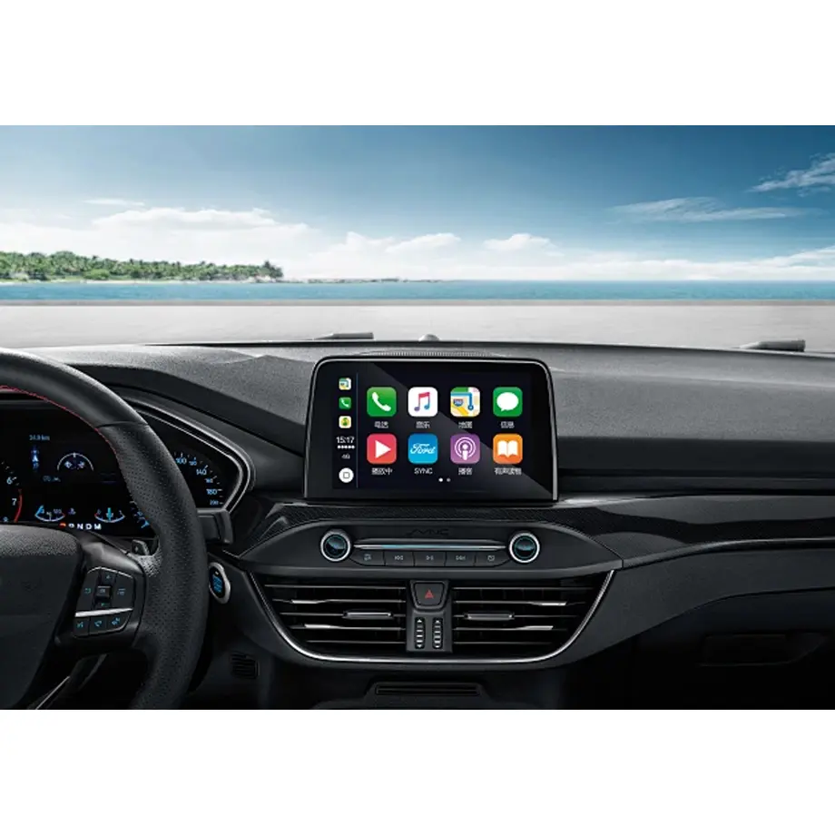
Model P/N
Size
Resolution
Brightness
Viewing Angle
Connector Type
Operating Temp
Overall(mm)
samsung
AMSA57ZU03-0
Brand
Panel Size (inch)
Model P/N
Resolution
Brightness (nits)
Viewing Angle
Contrast Ratio
Response Time
Overall (mm)
Active Area (mm)
Refresh Rate
Display Colors
Panel Type
Connector Type
Surface Treatment
Operating Temp
Touchscreen Type
Storage Temp
Work Mode
Pixel Format
Input Voltage (V)
Touch Interface
Weight (g)
Designed For
Product Details
Product Overview
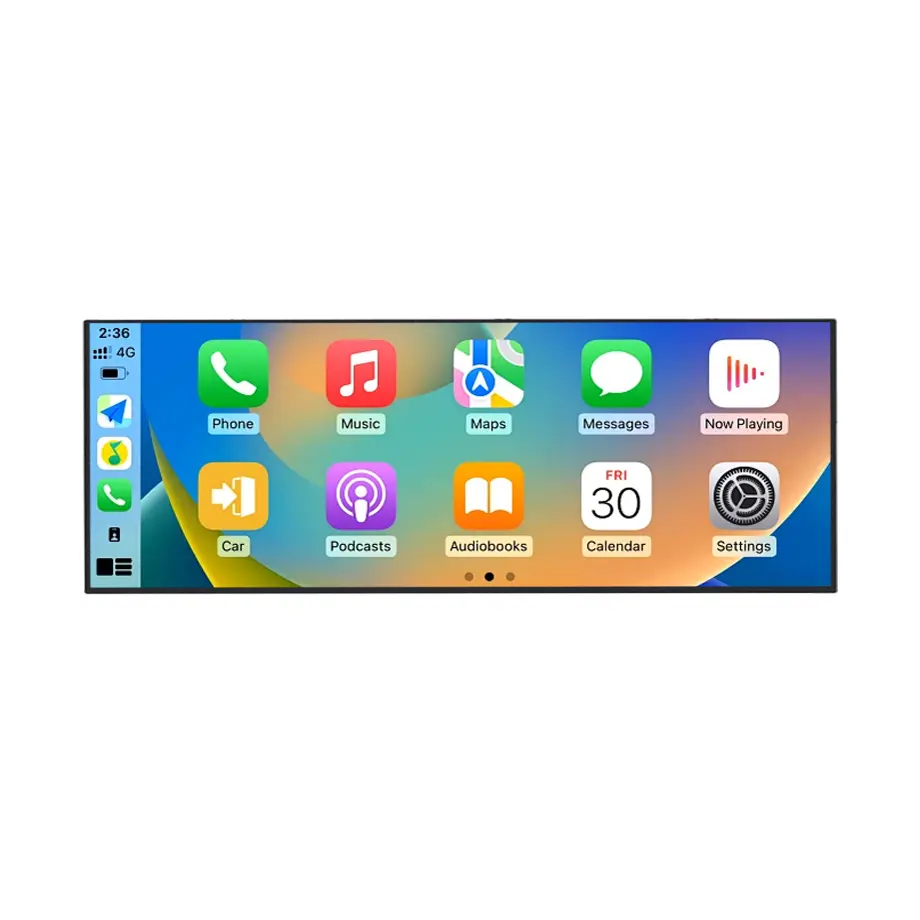
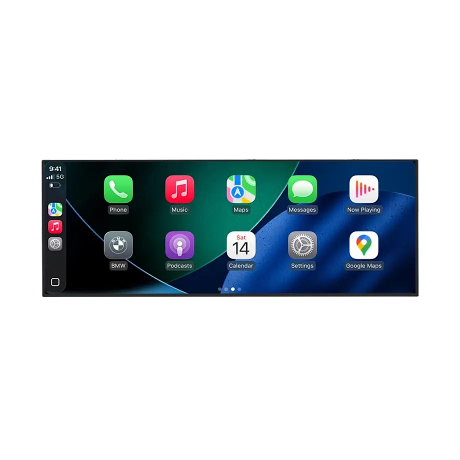
AMSA57ZU03-0 DCI-P3 Automotive OLED Module is a 15.7-inch Samsung Display AM-OLED full module designed for automotive display integration. It combines 2880(RGB)×1620 resolution in a 16:9 format with 670 cd/m² typical luminance, 16.7M colors at 99% DCI-P3, and an On-Cell Touch implementation using I²C. The module is self-emissive, so it does not require a conventional LCD backlight stack, and its 1 ms typical gray-to-gray response gives system designers a fast optical starting point for dynamic cockpit interfaces.
The active area is 346.46 × 194.89 mm, with a 352.66 × 202.84 × 6.58 mm outline and a 250 g typical panel weight. Native display connectivity is four-lane eDP on a 100-pin connector. The supplied power information lists several model-specific rails—1.8 V, 3.3 V, 4.3 V, 5.0 V and 8.0 V for identified internal domains—so it must not be simplified into a single generic input-voltage claim.
Samsung Display presents OLED as a technology for automotive cockpit experiences on its automotive OLED information. For the embedded display link, VESA's Embedded DisplayPort material provides interface-level engineering context. Neither reference changes the model-specific facts or establishes vehicle qualification by itself.
Three Core Buyer Value Propositions
1. Self-emissive OLED contrast with a 99% DCI-P3 color target
The module's AM-OLED architecture is self-emissive and is specified with a 2,000,000:1 typical contrast ratio plus 99% DCI-P3 color coverage. For an automotive HMI designer, that provides a strong starting point for dark UI themes, maps, media, status graphics and layered cockpit content where black-level separation and color saturation are important. Finished-vehicle color, reflection and readability still depend on cover glass, coatings, calibration, ambient light and installation angle.
2. Integrated On-Cell Touch reduces front-stack interfaces
On-Cell Touch is confirmed for this module, with I²C listed as the touch interface. Combining display and touch at the panel level can reduce the need for a separate add-on touch sensor and its independent mechanical stack. It does not prove a complete vehicle touch controller implementation, glove behavior, wet-finger performance, EMC robustness or cover-lens construction. Those characteristics need project-specific validation using the exact touch firmware and front glass.
3. -30 °C to 85 °C operating range supports wider thermal planning
The confirmed operating range is -30 °C to 85 °C, with storage from -40 °C to 95 °C. Those limits give an integrator a wider component envelope than a typical indoor panel and make the module relevant to temperature-varying vehicle interiors. Temperature range alone is not proof of automotive grade, qualification to any OEM or transport standard, or guaranteed performance in a particular cockpit location. The complete system must be validated against the target program requirements.
Key Specifications at a Glance
| Parameter | Confirmed value |
|---|---|
| Manufacturer / model | Samsung AMSA57ZU03-0 |
| Display size | 15.7 inch |
| Display technology | AM-OLED, full module |
| Resolution | 2880(RGB)×1620, 16:9 |
| Pixel layout | S-Stripe RGB |
| Active area | 346.46 × 194.89 mm |
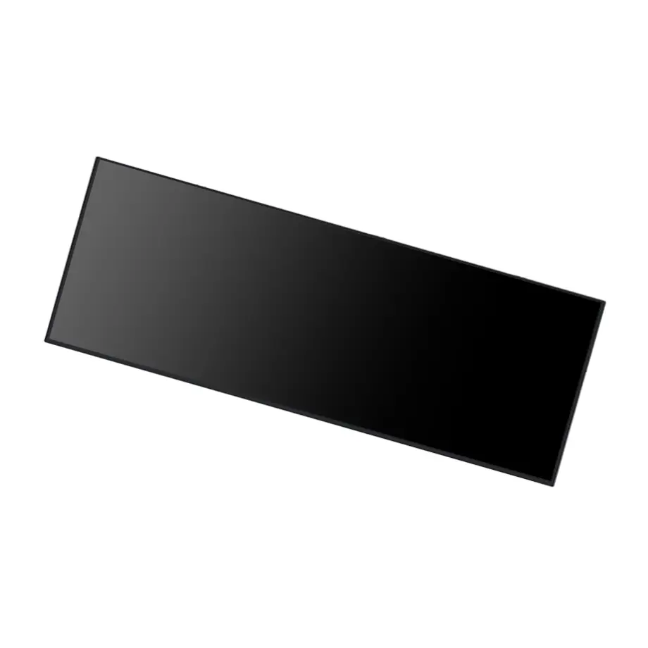
| Outline | 352.66 × 202.84 × 6.58 mm |
| Brightness | 670 cd/m² typical |
| Contrast ratio | 2,000,000:1 typical |
| Display colors | 16.7M, 99% DCI-P3 |
| Response time | 1.0 ms typical G-to-G |
| Refresh rate | 60 Hz |
| Native interface | eDP, 4 lanes, 100-pin connector |
| Touch | On-Cell Touch, I²C |
| Operating / storage temperature | -30 to 85 °C / -40 to 95 °C |
| Surface | 3H hard coating |
What Does Self-Emissive OLED Change for Cockpit Design?
Unlike an LCD module, an OLED display generates light at each pixel and therefore does not rely on a separate WLED backlight, light guide and diffuser stack. For AMSA57ZU03-0 DCI-P3 Automotive OLED Module, this reduces the number of optical layers that an LCD assembly would normally need behind the image plane. It also changes the engineering questions. Power varies with image content, local luminance is controlled at the pixel level, and thermal behavior must be evaluated across realistic UI patterns rather than from a single backlight setting.
The 2,000,000:1 typical contrast ratio is a panel measurement, not a finished-cockpit guarantee. Reflections from the cover lens, air gaps, anti-reflection treatment, dashboard geometry and incident sunlight can reduce perceived contrast. If the display sits near a windshield or glossy trim, evaluate the complete front stack under the actual angular light conditions and with both dark and bright user-interface themes.
Color and lifetime boundaries
The module is specified for 16.7 million colors at 99% DCI-P3. That provides useful wide-gamut capability for a rich interface, but the finished system should still define its color space, gamma, white point and calibration tolerances. The listed self-emissive light-source life is 10,000 hours in the supplied data. Because OLED lifetime depends strongly on luminance, temperature and image content, procurement and engineering should confirm the manufacturer's lifetime test basis before converting that figure into a vehicle service-life expectation.
How Should the 100-Pin eDP and Multi-Rail Power Be Integrated?
The panel-side video interface is four-lane eDP on a 100-pin connector. System designers should obtain the exact pin assignment and timing for the production revision, then confirm the controller's lane configuration, AUX behavior, power-up sequence and supported native mode. The module is not a finished HDMI, DisplayPort or USB-C monitor, so external host connectivity depends on the selected cockpit computing platform or bridge architecture.
Power deserves particular attention because the supplied specification lists multiple rails: 1.8 V, 3.3 V, 4.3 V, 5.0 V and 8.0 V associated with internal domains such as LSVDD, TCONVDD, PMVDD, ELVDD and VBAT. Do not collapse those values into a single “input voltage.” The system power architecture must provide the correct rails, tolerances and sequencing defined by the exact module documentation.
Prototype validation
During sample approval, exercise the native 2880×1620 mode through cold start, warm restart, sleep/wake and repeated touch activity. Observe image stability, power-rail behavior and touch reporting across the intended temperature range. Cable routing and connector retention should be tested in the actual packaging because the 100-pin interface and touch wiring share a compact cockpit environment with switching power electronics and other high-speed buses.
How Should On-Cell Touch Be Qualified in a Vehicle HMI?
The confirmed touch implementation is On-Cell Touch with I²C, which gives the project a defined interface boundary. The I²C controller path still requires firmware integration, interrupt handling, coordinate mapping and power-state management at the host. Touch functionality should be verified through the target cover lens and mechanical stack because glass thickness, adhesive, grounding and nearby conductive structures can change sensing behavior.
No claim is made here for glove operation, wet-finger detection, stylus support, force sensing, haptic feedback, EMI immunity or a particular touch service life. Those features are not established by the supplied model evidence. If they are required by the vehicle program, put them into the sample acceptance plan and request model-specific documentation rather than assuming they are standard because the module has On-Cell Touch.
The touch stack also affects optical performance. A cover lens can change reflectance and black appearance, while bonding choices can influence parallax and mechanical stress. Evaluate display readability and touch response together in the assembled stack, especially at the temperature extremes that matter to the project.
Which Automotive Qualification Boundaries Matter?
The supported application is Automotive Display, and same-model public information also describes the module for vehicle use. That application evidence is sufficient to position AMSA57ZU03-0 DCI-P3 Automotive OLED Module for automotive display integration, but it does not by itself prove automotive-grade certification, AEC-Q qualification, ISO 16750 compliance, a specific OEM validation or an exact vehicle fit. Those are separate program-level or component-level qualification questions.
For a cockpit project, confirm operating and storage temperature, vibration requirements, dimming behavior, brightness control, cover-lens stack, optical bonding status, electromagnetic compatibility and production-change requirements against the target system specification. The current product evidence confirms temperature range, brightness, touch and interface facts; it does not establish every environmental or regulatory requirement of a vehicle program.
Lifecycle and replacement planning
The same-model source describes the part as in production, but current production status and supplier stock are time-sensitive. They should be treated as sourcing evidence rather than a guaranteed supply duration. Before an automotive design freeze, request the latest production status, target program volume assumptions, change-notification expectations and any end-of-life communication process needed by the buyer.
Where Can a 15.7-Inch 16:9 OLED Module Fit?
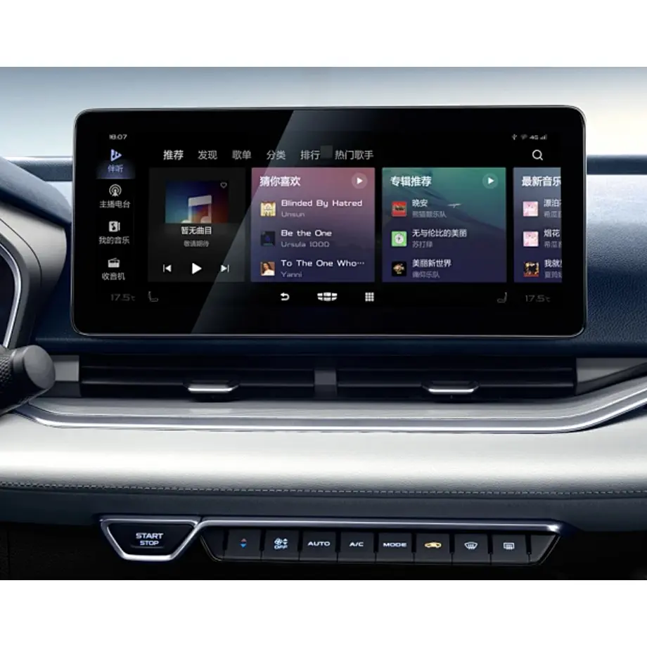
The confirmed automotive application and wide 15.7-inch format make the module relevant to central information displays, passenger information interfaces, secondary cockpit displays and other in-vehicle HMI concepts where the mechanical envelope and qualification plan fit. These are application scenarios, not declarations that the module is approved for a particular vehicle platform. The supplied source's reference to a specific vehicle brand should not be treated as a guaranteed fit or endorsement.
The 346.46 × 194.89 mm active area and 352.66 × 202.84 mm outline give mechanical teams concrete dimensions for early packaging studies. At only 6.58 mm overall depth and 250 g typical weight, the module can support slim cockpit concepts, but final mounting, cover glass, support structure and connector clearance still need the manufacturer's mechanical drawing.
What Should Procurement and Engineering Confirm Before SOP?
Start with the exact AMSA57ZU03-0 identity and request the latest Samsung specification, mechanical drawing and interface details. Confirm the 100-pin eDP mapping, all required power rails, touch I²C integration and the 2880×1620 timing. Define the intended cover lens and bonding approach before optical testing because the front stack can materially affect reflections, touch behavior and thermal stress.
For environmental qualification, do not use the -30 to 85 °C operating range as a substitute for the complete vehicle requirement. Build a matrix covering the buyer's target temperature, vibration, EMC/ESD, brightness/dimming, touch, optical and mechanical criteria. Any undocumented item should remain a confirmation task rather than being converted into an unsupported claim.
Finally, define sourcing requirements separately from technical capability. Current stock and production indications can help plan samples, but automotive programs usually require change control and longer horizon planning. Ask for current lifecycle information and the buyer's required notification process before volume commitment.
Procurement Checklist
- Confirm Samsung AMSA57ZU03-0 model and current production revision.
- Validate four-lane eDP timing and the 100-pin connector assignment.
- Verify each listed power rail and its sequencing rather than using one generic voltage.
- Integrate On-Cell Touch through the confirmed I²C interface and qualify the final cover stack.
- Check the 352.66 × 202.84 × 6.58 mm outline against the cockpit package.
- Test optical readability, touch response and thermal behavior across project conditions.
- Request qualification evidence required by the target vehicle program; do not infer it from the application label.
- Confirm current production, lifecycle and change-notification information before SOP.
AMSA57ZU03-0 DCI-P3 Automotive OLED Module provides a high-resolution, wide-gamut, touch-integrated OLED platform for automotive display projects. Successful deployment depends on system-level power, interface, front-stack, environmental and qualification validation for the specific vehicle program.
Recommended: Same Size
(15.7")
Applications & Value of LCD Panel

- Fast sourcing with in-stock panels & cross-reference alternatives
- Stable supply chain with long-term availability
- Engineering-level support from panel to integration
- Custom solutions: cable, touch & optical bonding
- Strict quality control with IQC / OQC / aging test
- Full traceability system for quality assurance
- Complete technical documentation & drawings
- Compliance support: RoHS & certification files
