~
~
~
~
~
~
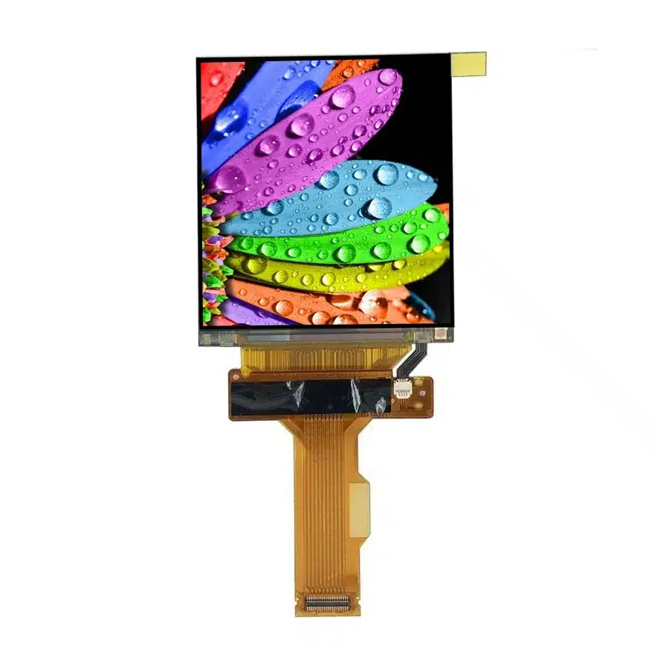
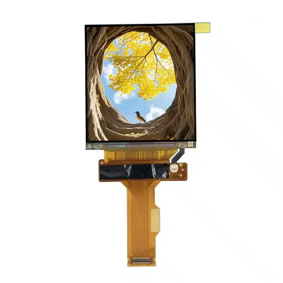
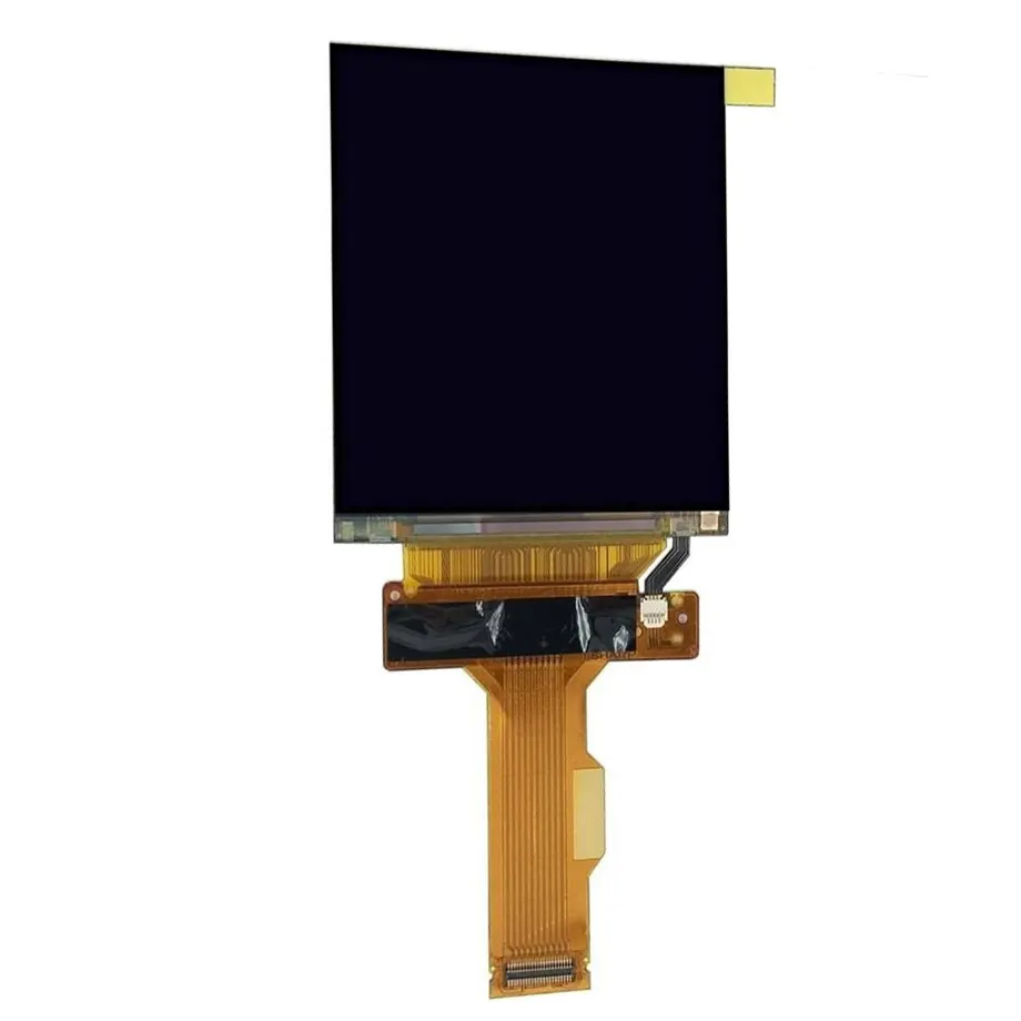
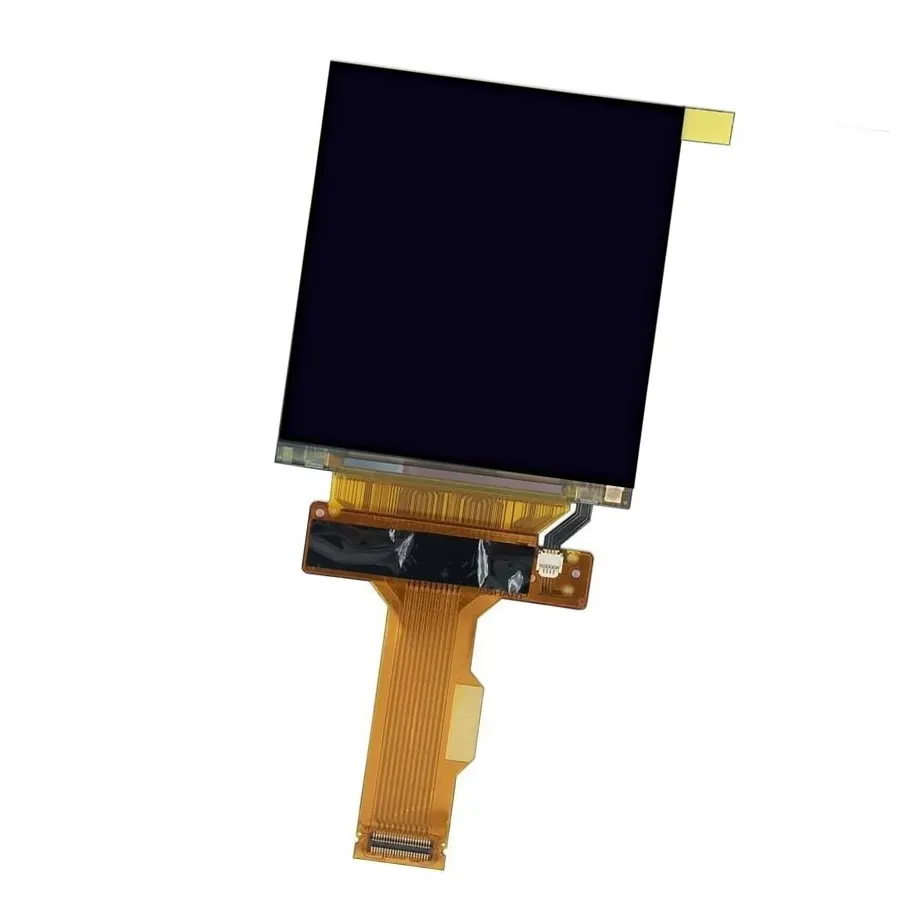
LS030B3SX01 Camera MIPI Touch LCM Sharp
Model P/N
Size
Resolution
Brightness
Viewing Angle
Connector Type
Operating Temp
Overall(mm)
sharp
LS030B3SX01
Brand
Panel Size (inch)
Model P/N
Resolution
Brightness (nits)
Viewing Angle
Response Time
Overall (mm)
Active Area (mm)
Refresh Rate
Display Colors
Panel Type
Connector Type
Operating Temp
Touchscreen Type
Storage Temp
Work Mode
Pixel Format
Designed For
Product Details
LS030B3SX01 Camera MIPI Touch LCM is a compact 3.0-inch Sharp LTPS TFT-LCD module developed for digital still camera display integration. The exact-model record combines a 900×600 native image, 630 cd/m² typical luminance, 16.7 million colors, WVA normally-black transmissive operation, an integral WLED backlight and In-Cell Touch. Its active area is 62.37 × 41.58 mm within a 72.26 × 54 mm outline, and the native display interface is identified as MIPI. Several electrical and environmental fields are not established in the current exact-model evidence, so voltage, detailed lane count, touch protocol, refresh rate, response time and temperature limits remain unresolved instead of being borrowed from another Sharp model.
Camera-first display architecture
A digital still camera imposes different priorities from a laptop or industrial HMI. The display must fit a small mechanical envelope, present detailed live-view and menu information, and work with a tightly integrated imaging processor and power budget. The documented application for this model is Digital Still Camera, so the public scope remains centered on camera display integration. The page does not extend the part into medical, automotive or rugged applications without same-model evidence.
The 900×600 format uses a 15:10 aspect ratio and RGB vertical-stripe layout. On a 3-inch diagonal, that creates a high-density image suitable for compact camera user interfaces and image review. The module is not claimed to be a complete electronic viewfinder subsystem or a guaranteed replacement for a named camera. Connector pinout, MIPI timing, initialization commands, touch communication and mechanical mounting still need exact product documentation.
Three Core Buyer Value Propositions
1. 630-nit panel luminance gives camera designers useful brightness headroom
The specified 630 cd/m² typical luminance provides a strong starting point for a small camera display that may be used under changing ambient light. It is appropriate to describe the module as high-brightness relative to many compact displays, but brightness alone does not prove sunlight-readable performance. Cover materials, reflections, optical bonding, backlight drive and automatic brightness strategy will determine how the finished camera screen performs outdoors.
2. In-Cell Touch integrates interaction without a separate generic touch overlay
Touch capability is part of the exact module description. That can help reduce front-stack complexity in a camera design compared with adding an unrelated external sensor. The current evidence does not identify the touch host interface, controller protocol, point count, glove behavior or stylus support. Those values remain blank and should be obtained from Sharp documentation before a processor, FPC or software driver is finalized.
3. MIPI aligns with compact embedded image-processing platforms
The source identifies MIPI as the display signal interface, which is common in mobile and camera-class embedded architectures. The exact model evidence does not establish lane count, DSI revision, connector pinout or initialization sequence, so those details must not be inferred from other 3-inch modules. The practical buyer value is architectural direction: a MIPI-capable host can be shortlisted, then validated against the exact Sharp electrical and command specification.
Key Specifications at a Glance
| Specification | LS030B3SX01 value |
|---|---|
| Display size | 3.0 inch |
| Panel type | LTPS TFT-LCD, LCM |
| Resolution | 900×600, 15:10 |
| Active area | 62.37 × 41.58 mm |
| Outline | 72.26 × 54 mm |
| Brightness | 630 cd/m² typical |
| Colors | 16.7M |
| Display mode | WVA, Normally Black, Transmissive |
| Backlight | WLED |
| Touch | In-Cell Touch |
| Display interface | MIPI |
| Documented application | Digital Still Camera |
What remains unresolved in the exact-model evidence?
The current exact-model record does not provide safe values for contrast ratio, viewing angle, response time, refresh rate, mass, thickness, supply voltage or operating/storage temperature. It also does not provide the exact touch communication interface. Those gaps matter because a visually similar Sharp panel or another LS-series module can use different electrical and mechanical details. Blank production fields are intentional evidence boundaries, not missing marketing opportunities.
Engineering should request the current Sharp specification and mechanical drawing before PCB or enclosure release. The required document set should identify connector and pin assignment, MIPI lane configuration, power rails and sequencing, reset timing, command initialization, backlight drive, touch signaling and full mechanical tolerances. A camera platform should not be frozen around assumptions copied from a related module.
MIPI bring-up for a compact camera display
LS030B3SX01 Camera MIPI Touch LCM should be evaluated with the target imaging processor or bridge under the native 900×600 timing. Bring-up needs more than a single successful boot: repeat power cycles, sleep/wake transitions, camera mode changes and prolonged live-view operation. Watch for line artifacts, color-order errors, intermittent blanking and initialization failures. The approved command sequence and host firmware should be configuration-controlled with the module revision.
If a processor vendor supplies a generic MIPI display example, treat it as a starting framework rather than proof of compatibility. The exact module may require product-specific reset timing, register programming, clock behavior or power sequencing. These requirements should come from the exact Sharp documentation or a validated reference design for LS030B3SX01.
Touch integration must be verified independently from the video link
In-Cell Touch describes the physical integration of the touch function but does not establish the host protocol. The touch path may require separate interrupt, reset and data lines from the display video connection. During development, test coordinate mapping, edge response, orientation, menu gestures, sleep/resume behavior and any camera-specific touch interactions. Touch accuracy should be checked after the final cover and bezel are installed because mechanical pressure and optical stack changes can affect capacitive performance.
The page does not claim multi-touch count, stylus capability, glove support or wet-touch operation. If any of those features are required, they should become explicit qualification items tied to exact-model documentation and sample testing.
Optical stack choices for image review and menu visibility
The 630-nit module brightness provides headroom, but the camera's front surface determines a large part of real-world visibility. Cover-window reflectance, air gap, adhesive, surface coating and enclosure shading all affect contrast in bright environments. A bonded construction can behave differently from an air-gapped one even with the same LCD module. Designers should measure the complete front stack under representative indoor and outdoor illumination.
Color performance is specified only as 16.7 million colors in the current source. No exact sRGB, Adobe RGB or DCI-P3 coverage is confirmed, so those percentages should not be invented. Camera image review also depends on processing, gamma and white balance in the host. If accurate preview color is a product requirement, define a system-level measurement plan rather than treating color depth as calibration evidence.
Mechanical packaging in a 3-inch camera body
The 72.26 × 54 mm outline and 62.37 × 41.58 mm active area provide the key known geometry. Full thickness is unresolved, which means rear clearance and connector keep-out cannot be finalized from the current record alone. Obtain the exact drawing before tooling a camera rear cover or hinge structure. The small module should be supported without localized pressure on the active area or touch-integrated glass.
Prototype builds should inspect bezel overlap, cable bend, connector access and touch performance after assembly. A camera experiences frequent handling and may see point loads from buttons, grips or hinged screens, so the display mounting structure should isolate the panel from chassis stress. Any rotating or tilting display mechanism requires its own cable-flex and endurance validation.
Application fit: digital still camera display integration
Digital Still Camera is the documented exact-model application. That supports use in camera rear displays, menu screens and related camera viewing functions when the host can meet the MIPI, touch, power and mechanical requirements. The evidence does not establish compatibility with a specific DSLR, mirrorless camera or industrial imaging system. Exact replacement work should match the original part number and connector architecture.
The combination of LTPS, compact size, 630-nit luminance and integrated touch can also make the module technically interesting for other compact embedded concepts, but such uses remain potential engineering evaluations rather than confirmed applications. Public application copy therefore stays centered on the documented camera use.
Procurement and incoming-quality controls
Confirm LS030B3SX01 on the incoming label and compare the module outline, active image and touch-integrated construction to the approved sample. Record the production revision and keep it associated with the validated host firmware. If the supplier proposes a substitute, do not approve it based only on 3-inch size, 900×600 resolution or MIPI terminology; command sets, connectors, touch path and optics can differ.
LS030B3SX01 Camera MIPI Touch LCM should be released for volume purchasing only after the target camera platform has demonstrated repeatable display startup, stable live view, touch behavior and mechanical fit. Optical acceptance should include brightness, visible defects and performance through the final cover. Commercial availability, lead time, MOQ and lifecycle need separate current sourcing confirmation.
Sample qualification priorities before camera enclosure freeze
For the first engineering lot, use a checklist that separates electrical bring-up from user-facing image quality. Confirm repeatable power sequencing and native image timing first, then verify touch response with the actual cover window, and only after that record optical measurements under representative camera brightness settings. This sequence helps isolate whether a failure comes from host control, touch integration or the front optical stack. Keep the accepted sample, firmware build and mechanical configuration together so later supplier lots can be compared against a controlled reference.
Engineering summary
LS030B3SX01 Camera MIPI Touch LCM combines a 3-inch 900×600 LTPS LCD, 630 cd/m² typical luminance, WLED illumination, MIPI video and integrated In-Cell Touch for digital still camera applications. Its confirmed strengths are compact geometry, high panel luminance and an integrated interaction layer. The unresolved electrical, touch-protocol and environmental details should remain unresolved until exact Sharp documentation is available, keeping camera integration decisions tied to evidence rather than family assumptions.
Recommended: Same Size
(3")
Applications & Value of LCD Panel

- Fast sourcing with in-stock panels & cross-reference alternatives
- Stable supply chain with long-term availability
- Engineering-level support from panel to integration
- Custom solutions: cable, touch & optical bonding
- Strict quality control with IQC / OQC / aging test
- Full traceability system for quality assurance
- Complete technical documentation & drawings
- Compliance support: RoHS & certification files