
Freya Yang
+86 18318948097
+852 62667476
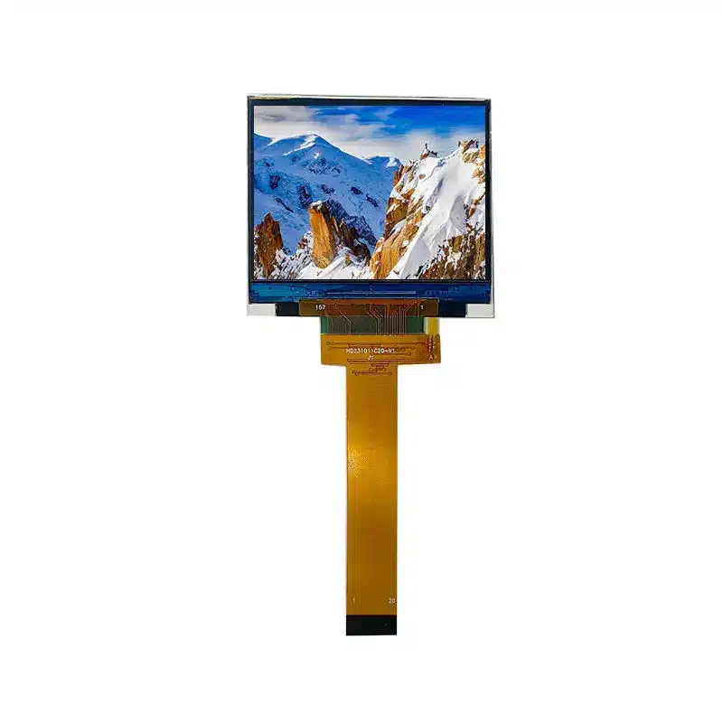
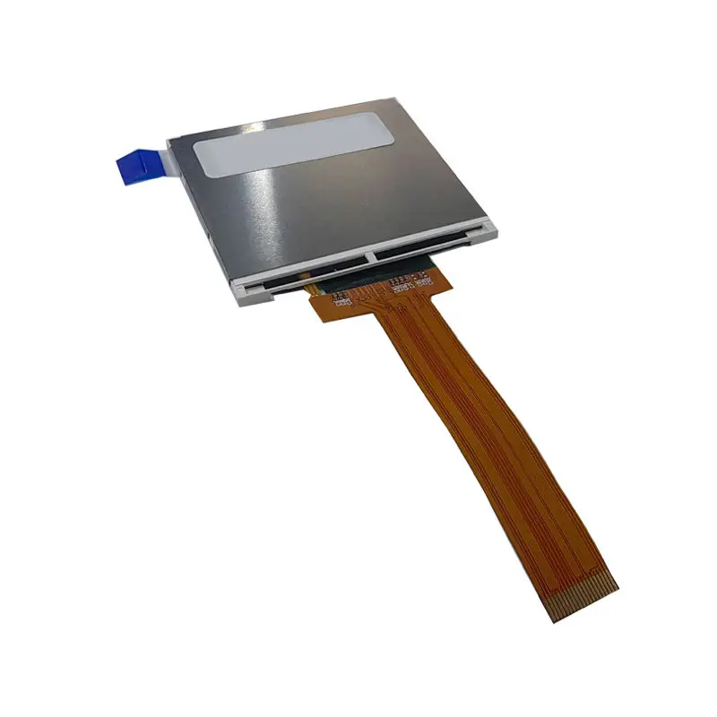
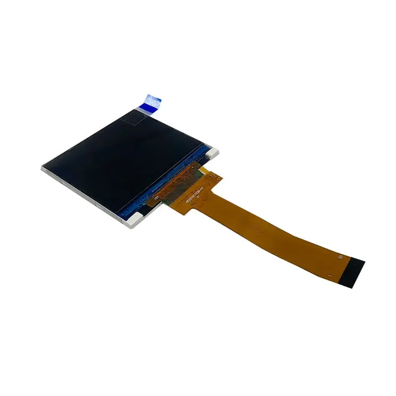
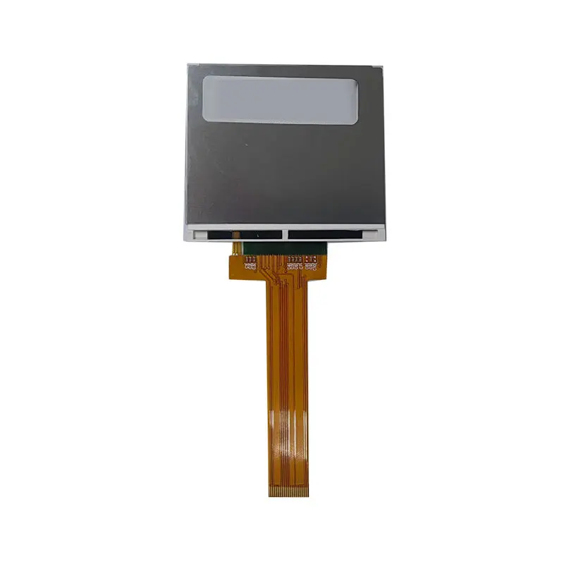
2.31 Inch Medical Device QVGA Display Module with SPI
Model P/N
Size
Resolution
Brightness
Viewing Angle
Connector Type
Operating Temp
Overall(mm)
huisoar
HS023QT04A-V1
Brand
Panel Size (inch)
Model P/N
Resolution
Brightness (nits)
Viewing Angle
Contrast Ratio
Response Time
Overall (mm)
Active Area (mm)
Refresh Rate
Bezel Opening
Display Colors
Panel Type
Connector Type
Operating Temp
Touchscreen Type
Storage Temp
Work Mode
Pixel Format
Input Voltage (V)
Operating Environment
Designed For
2.31 Inch Medical Device QVGA Display Module with SPI
This compact 320 × 240 TFT display uses a 20-pin four-wire SPI connection for space-constrained medical and precision-instrument interfaces.
Product Summary
The Medical Device QVGA Display Module is a compact 2.31-inch TFT component for diagnostic instruments, portable monitoring controls, laboratory equipment and other products that need a clear 320 × 240 graphical interface within a restricted front-panel area. Its QVGA raster supports text, numerical results, status icons, menus, trend graphics and alarm indications without the mechanical demands of a larger display.
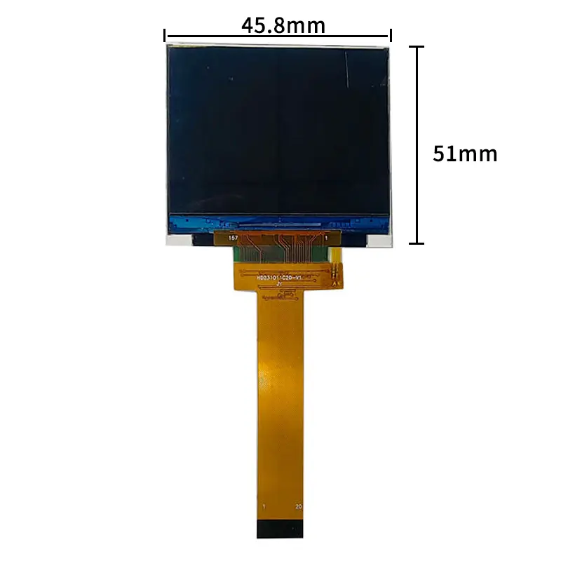
The active image area measures 46.75 × 35.06 mm within a 51.00 × 45.8 mm module outline. The display uses a 20-pin FPC and a four-wire SPI communication path, while the product configuration identifies ILI9342C as the driver IC. Standard luminance is 350 cd/m², the display mode is normally black, and the gray-inversion viewing direction is specified at 12 o’clock.
This is a component-level display rather than a finished medical monitor. The host controller, power design, backlight driver, enclosure, protective front, software and regulatory qualification remain part of the completed equipment design.
Key Specifications
| Parameter | Confirmed Value |
|---|---|
| Display size | 2.31 inches |
| Native resolution | 320 × 240 pixels |
| Resolution class | QVGA |
| Panel structure | a-Si TFT active matrix |
| Display mode | Transmissive, normally black |
| Luminance | 350 cd/m² |
| Viewing direction | 12 o’clock gray-inversion direction |
| Display colors | 262K colors |
| Pixel pitch | 0.1461 × 0.1461 mm |
| Active area | 46.75 × 35.06 mm |
| Module outline | 51.00 × 45.8 mm; thickness requires confirmation |
| Connector | 20-pin FPC |
| Display interface | Four-wire SPI |
| Driver IC | ILI9342C identified |
| Backlight | Four white LEDs |
| Operating temperature | −20°C to +70°C |
| Touch | Not confirmed |
QVGA Interface Design and Optical Performance
Native 320 × 240 UI Planning
The native 320 × 240 raster should be used directly for the equipment interface. Purpose-built QVGA graphics preserve character edges, icon proportions and line weights more effectively than artwork scaled down from a larger display format.
The 4:3 image area can be divided into a primary measurement region, status indicators, operating prompts, alarm messages and navigation controls. For small medical or analytical instruments, this structure provides enough room for clear numerical presentation while keeping the enclosure compact.
Orientation should be fixed before software and tooling are released. The host coordinate system, scan direction, graphical assets and FPC route must match the approved module orientation.
350 cd/m² Lighting Boundary
The standard 350 cd/m² configuration is intended primarily for indoor or controlled-light equipment. Perceived brightness depends on the front window, cover-lens transmission, surface reflections, air gaps, bonding, tint and installation lighting.
The 350 cd/m² panel should be tested behind the final cover under actual installation lighting.
This value does not establish sunlight readability, outdoor visibility or compliance with a medical-display luminance requirement. A different optical target requires a separately approved configuration and system-level verification.
12 O’Clock Viewing Direction
The module specifies a 12 o’clock gray-inversion viewing direction. This describes the direction associated with the display’s optical inversion behavior; it is not a full viewing-angle specification.
The intended operator position should therefore be compared with the installed orientation. A device viewed mainly from above, below or at an angle may require sample testing in the final housing before the front-panel design is approved.
Integrating the Medical Device QVGA Display Module
20-Pin Four-Wire SPI Qualification
A 20-pin FPC does not guarantee SPI timing, voltage, pin mapping or connector compatibility.
Engineering should confirm the complete pin assignment, FPC pitch, contact side, connector orientation, logic levels, panel supply, clock target, chip-select behavior, data direction, reset control, command/data selection and backlight connections. Another 20-pin SPI panel may use a different electrical or mechanical definition.
The interface should also be evaluated against the required screen-update rate. Four-wire SPI is practical for compact instrument UIs, but full-screen animation or rapid waveform updates may impose different bandwidth requirements than static values, menus and status graphics.
ILI9342C Software Boundary
ILI9342C identification does not guarantee a drop-in software library or module initialization sequence.
The approved command table should define the required interface mode, pixel format, scan direction, orientation, display inversion, sleep and wake behavior, frame-memory settings and any module-specific parameters. Generic code written for a different ILI9342C panel should not be treated as production-ready without comparison against the ordered module documentation.
SPI and MIPI Conflict Resolution
The exact-model information identifies a four-wire SPI interface. The supplied marketplace information also contains a MIPI field and a combined SPI/MIPI title, creating an unresolved conflict.
MIPI support is not confirmed for the exact MTF023QT04A-V1 configuration.
The production specification should identify one approved interface route, one FPC definition and one software package. A host that only provides MIPI DSI should not be connected on the assumption that the marketplace category field applies to the ordered SPI module.
Mechanical Integration and Backlight Planning
Active Area and Module Outline
The visible active area is 46.75 × 35.06 mm, and the confirmed two-dimensional outline is 51.00 × 45.8 mm. The final drawing must also define module thickness, FPC length, stiffener dimensions, bending limits, connector position, locating tolerances and permitted support areas.
The enclosure opening should be designed from the approved active-area and outline drawing rather than the nominal diagonal alone. Front-window overlap, adhesive width, support pressure and FPC clearance can affect both appearance and reliability.
The separate 154.21 × 85.92 mm active-area value is inconsistent with the module outline and should not be used for tooling.
Four-LED Backlight Requirements
The backlight uses four white LEDs, but the available data does not define the voltage, current, series/parallel topology, driver type, dimming method or lifetime.
A backlight circuit should not be released from LED count alone. Engineering requires the complete electrical limits, current-regulation method, enable behavior, dimming requirement, startup condition and thermal allowance for the approved module.
Medical and Instrument Application Boundaries
The Medical Device QVGA Display Module can be evaluated for portable diagnostic instruments, compact monitoring controls, laboratory analyzers, handheld test equipment and other precision interfaces that use a small QVGA screen.
Medical-device application wording does not establish regulatory certification or diagnostic-display qualification.
The finished product must define its own optical requirements, failure behavior, alarm presentation, electrical safety, EMC performance, environmental limits, software controls, cleaning method, usability criteria and regulatory documentation. The module’s −20°C to +70°C operating range is a component limit and does not qualify the complete equipment for every environment within that range.
Industrial instruments may use the same display architecture for measurements, menus and status information, provided SPI bandwidth, viewing orientation, enclosure fit, front-window optics and operating conditions are validated.
Customization and Procurement
Project evaluation may cover FPC length and shape, pin definition, connector orientation, SPI configuration, brightness target, backlight design, cover lens, optical treatment, optional touch development, enclosure adaptation, branding and packaging.
Custom configurations are generally reviewed from 500 pieces, subject to tooling requirements, material availability and the requested specification. Sample and standard-module quantities are confirmed separately.
Before customization begins, provide the approved host architecture, complete interface requirements, enclosure drawing, front-window structure, lighting conditions, compliance requirements and production forecast.
Procurement Checklist
Confirm the following before sample or production approval:
- Approved HS023QT04A-V1 and MTF023QT04A-V1 documentation
- Native 320 × 240 timing and required orientation
- Four-wire SPI mode and target clock
- Complete 20-pin FPC assignment
- Panel supply and logic-voltage limits
- ILI9342C command and initialization package
- Pixel format and scan-direction requirements
- FPC pitch, contact side, stiffener and orientation
- 46.75 × 35.06 mm active area
- Approved 51.00 × 45.8 mm outline and module thickness
- Rejection of the conflicting 154.21 × 85.92 mm active-area value
- Confirmation that MIPI is not required or provision of a separate MIPI configuration
- 350 cd/m² front-stack readability
- 12 o’clock viewing orientation
- Four-white-LED voltage, current, topology, driver and dimming requirements
- Operating-temperature and environmental qualification
- Touch requirement or standard non-touch confirmation
- Medical, safety, EMC and regulatory documentation requirements
- Sample criteria, quantity and annual demand
FAQ
About 2.31 Inch Medical Device QVGA Display Module
What must be checked before connecting the display to a 20-pin SPI host?
Is MIPI supported by this exact module configuration?
Does ILI9342C mean an existing display library will work without changes?
Which dimensions should control the enclosure design?
What must be qualified before using the module in medical equipment?
What is the minimum order quantity (MOQ) for custom display solutions?
The MOQ for this custom display solution is For custom LCD modules, MOQs typically depend on the level of customization, such as interface, touch panel, or optical bonding. Standard modules may have lower MOQs, while fully custom designs often require higher quantities. To get the exact MOQ for the HS023QT04A-V1 or a tailored variant, please contact our sales team with your projected volume and requirements. We will provide a precise quotation and lead time based on your specifications.
What interface options are available (e.g., LVDS, eDP, MIPI) for your panels?
This 2.31-inch QVGA display module supports SPI and MIPI interfaces via a 20-pin FPC connector. The four-wire SPI is ideal for space-constrained designs, while MIPI offers higher bandwidth for graphics-intensive applications. If you need a different interface, we can discuss customization options, but please note that any interface change would require a new design and should be confirmed on request. For detailed pinout and electrical specifications, please refer to the datasheet or contact our engineering support.
Can you provide medical-grade displays with specific certifications (e.g., ISO 13485)?
However, as a TFT-LCD module designed for medical devices, it is built to meet standard quality and reliability requirements. If you require certification compliance for your medical application, please contact us with your target market and certification needs. We can provide documentation and discuss any necessary testing or adjustments. Exact certification status and availability should be confirmed on request, as it may vary by production batch and customization.
What touch screen technologies do you support (e.g., capacitive, resistive, in-cell)?
Touch functionality for this display is currently listed as TBD (to be determined). We support various touch technologies including capacitive, resistive, and in-cell, depending on the project requirements. For this module, we can integrate a touch panel upon request. Please specify your preferred touch type and any environmental or durability requirements, and we will advise on the best solution and feasibility.
What are the packaging options for shipping displays to prevent damage during transit?
We offer standard packaging designed to protect displays during transit, including anti-static bags, foam cushioning, and rigid cartons. For this 2.31-inch module, each unit is typically placed in an anti-static bag and packed with foam inserts to prevent shock and vibration. Custom packaging options, such as vacuum-sealed trays or custom foam cutouts, are available for high-volume orders. Please confirm your shipping volume and destination to ensure the most suitable packaging solution.
Freya Yang
+86 18318948097
