Freya Yang
+86 18318948097
+852 62667476
7 Inch High Brightness Capacitive Touch LCD Module for Industrial HMI
Model P/N
Size
Resolution
Brightness
Viewing Angle
Connector Type
Operating Temp
Overall(mm)
huisoar
HS070PRT45057
Brand
Panel Size (inch)
Model P/N
Resolution
Brightness (nits)
Viewing Angle
Contrast Ratio
Response Time
Overall (mm)
Active Area (mm)
Refresh Rate
Bezel Opening
Display Colors
Panel Type
Connector Type
Operating Temp
Touchscreen Type
Storage Temp
Work Mode
Pixel Format
Input Voltage (V)
Touch Interface
Weight (g)
Operating Environment
Designed For
7 Inch High Brightness Capacitive Touch LCD Module for Industrial HMI
A 7-inch 800 × 480 RGB display platform with a capacitive-touch configuration and a separately specified high-brightness version for industrial interfaces.
Product Summary
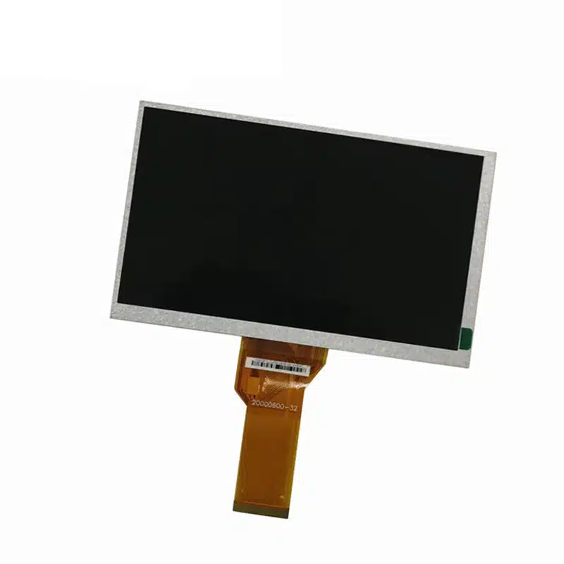
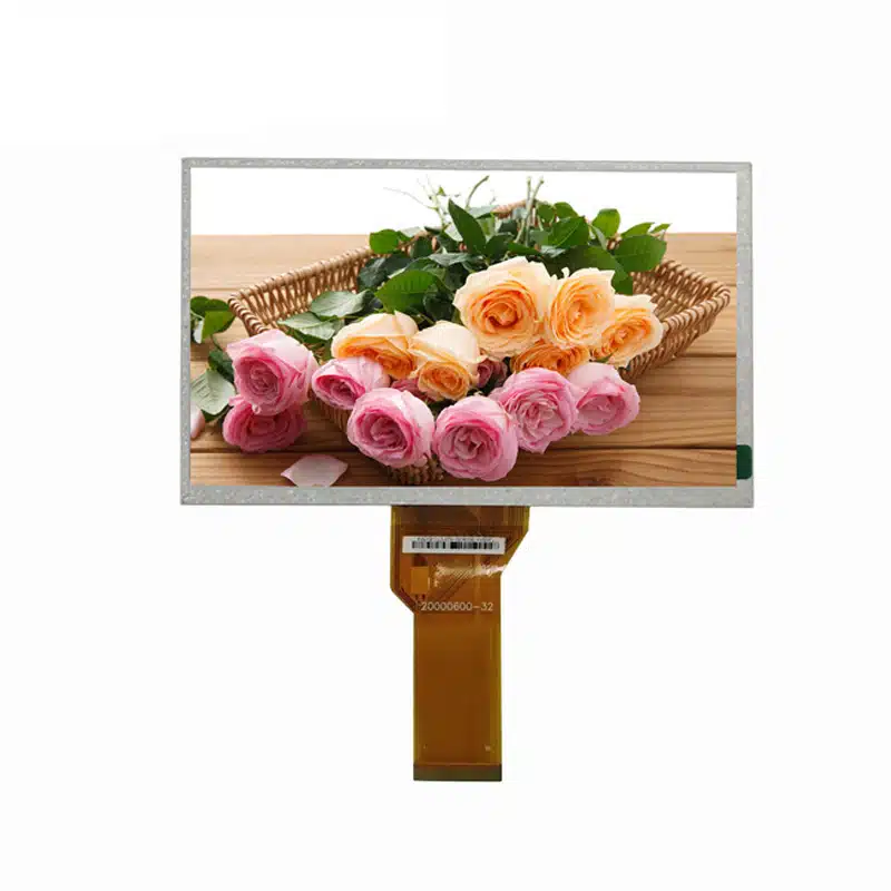
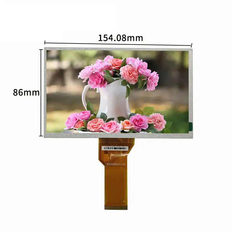
The High Brightness Capacitive Touch LCD Module is a landscape TFT platform for machine controls, kiosks and compact operator interfaces that need an 800 × 480 screen, native RGB image input and touch interaction. Its 154.08 × 85.92 mm active area fits a 164.9 × 100.0 mm module format, while separate base-LCM and touch-assembly depths support configuration-specific enclosure planning.
Two luminance versions are identified: a 400 cd/m² base version and a separate 1000 cd/m² high-brightness project version. The selected version must be fixed in the purchase specification rather than treated as a continuously adjustable range.
Key Specifications
| Parameter | Controlled value |
|---|---|
| Display size | 7 inches |
| Native resolution | 800 × 480 pixels |
| Display technology | TFT |
| Native image interface | RGB |
| Active area | 154.08 × 85.92 mm |
| Base-LCM size | 164.9 × 100.0 × 5.7 mm |
| Touch-configuration size | 164.9 × 100.0 × 7.82 mm |
| Standard brightness version | 400 cd/m² |
| High-brightness project version | 1000 cd/m² |
| Viewing direction | 12 o’clock |
| Touch | Capacitive-touch ordered configuration |
| Operating temperature | −20°C to +70°C |
| Storage temperature | −30°C to +80°C |
800 × 480 Interface and Viewing Planning
Prepare a Native Landscape UI
The 800 × 480 raster provides a conventional landscape workspace for status values, alarms, menus, equipment diagrams and touch controls. Interface artwork should be rendered natively to avoid blurred text or uneven scaling.
Touch targets, warning symbols and data fields should be tested on the physical 154.08 × 85.92 mm active area. The pixel resolution alone does not determine whether text and controls will remain legible at the final viewing distance.
Confirm the 12-O’Clock Orientation
The specified 12-o’clock viewing direction should be checked against the installed orientation. Enclosure rotation, operator height and screen tilt can change the perceived contrast of an asymmetric TFT structure.
A physical sample should be assessed from the intended operating position before the bezel, bracket or front cover is released.
High Brightness Capacitive Touch LCD Module Selection
Fix the Ordered Luminance Version
The 400 cd/m² base configuration and 1000 cd/m² project configuration should be managed as distinct ordered variants. The purchase specification should state the selected luminance, backlight implementation, current requirement, dimming method and acceptance tolerance.
The 1000 cd/m² panel value does not by itself establish sunlight readability. Cover glass, touch layers, bonding, reflections, thermal conditions and ambient light all affect the brightness delivered to the operator.
Validate the Finished Optical Stack
A capacitive sensor and cover lens can reduce transmission and increase reflections. Sample testing should use the intended:
- Cover-lens thickness
- Printed border
- Surface finish
- Bonding method
- Air gap or adhesive
- Backlight setting
- Installation lighting
Final acceptance should be based on the completed stack rather than the bare-panel rating.
RGB Host and FPC Integration
Qualify the Complete RGB Definition
A matching connector count does not establish RGB compatibility. Engineering must verify:
- RGB data width
- Pixel-clock frequency and polarity
- DE or synchronization mode
- Horizontal and vertical timing
- Signal voltage
- Reset and enable functions
- Complete FPC assignment
- Connector pitch and contact side
- Cable orientation
The native 800 × 480 timing should be supplied by the approved display documentation or matched controller firmware.
Separate the Native Panel from the External Board
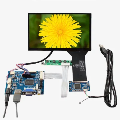
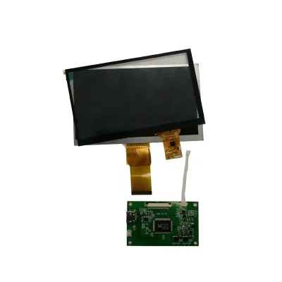
The panel’s native image path is RGB. An external board may convert HDMI, VGA, composite video or another host signal into RGB, but those ports belong to the board rather than the LCD itself.
Confirm the board model, populated connectors, firmware, input resolution, output timing, power input, cable set and inclusion status before quoting the product as a controller-equipped kit.
Capacitive-Touch Configuration
Treat Touch as a Separate Signal Path
The capacitive-touch control path requires its own controller, communication interface, voltage, interrupt/reset routing, firmware and pin map. RGB carries display pixels and should not be assumed to carry touch data.
The ordered touch specification should identify:
- Touch-controller model
- USB, I²C or other communication bus
- Supported touch-point count
- Touch FPC definition
- Operating voltage
- Coordinate orientation
- Cover-lens dimensions
- Firmware or tuning requirements
Approve the Combined Touch Drawing
The 5.7 mm base-LCM depth and 7.82 mm touch-configuration depth serve different mechanical purposes. The combined drawing must control enclosure tooling, front-window clearance, adhesive area, FPC exits and mounting support.
Do not release a touch enclosure from the base-LCM drawing alone.
Mechanical and Environmental Qualification
Check Active Area, Outline and Bezel Opening Separately
The 154.08 × 85.92 mm active area defines the visible image. The 164.9 × 100.0 mm outline defines the module envelope. A separate approved drawing is still required for the bezel opening, tolerances, FPC route and touch-lens overhang.
Mounting pressure should be distributed around approved support regions rather than applied to the active image area or flexible cables.
Use the Published Temperature Limits Correctly
The component is identified for operation from −20°C to +70°C and storage from −30°C to +80°C. These values do not establish humidity resistance, waterproofing, condensation tolerance, vibration performance or a finished-system environmental grade.
Application Scenarios
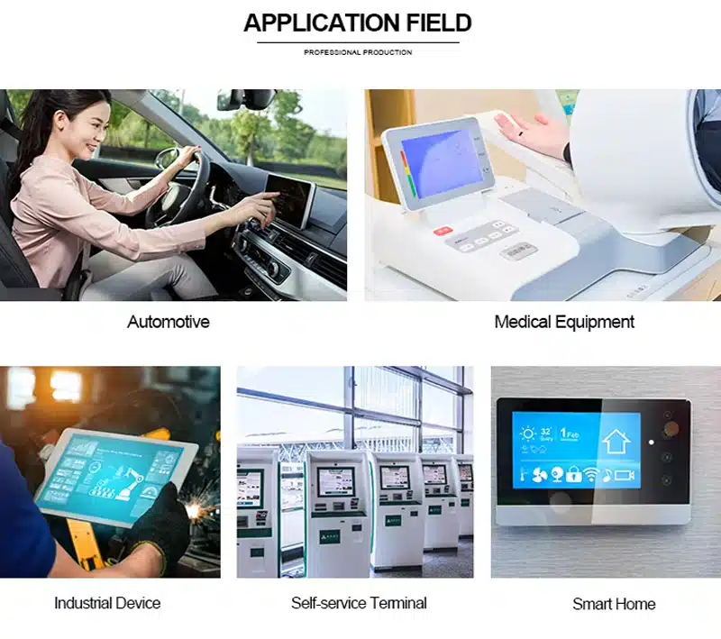
The High Brightness Capacitive Touch LCD Module can be evaluated for industrial HMI panels, machine controls, smart lockers, vending controls, building systems, self-service kiosks and compact equipment interfaces.
Use in outdoor equipment, vehicles, medical systems or regulated transaction devices requires separate finished-product qualification. The component specifications alone do not establish those approvals.
Customization and Procurement
Project review may cover:
- FPC geometry and RGB definition
- 400 or 1000 cd/m² version
- Capacitive-touch stack
- Cover glass and printed border
- Air or optical bonding
- Surface treatment
- Enclosure fit
- External controller-board matching
- Cable and connector requirements
Custom scope and quantity are confirmed after the electrical, optical and mechanical configuration is defined. Samples and standard-module quantities are quoted separately.
Procurement Checklist
- Assigned and supplier model references
- Selected 400 or 1000 cd/m² version
- Native 800 × 480 timing
- RGB data width and synchronization mode
- Complete FPC pin assignment
- Connector pitch, contact side and orientation
- Panel and backlight voltage/current
- Base-LCM and touch-assembly drawings
- 154.08 × 85.92 mm active area
- 5.7 mm or 7.82 mm applicable depth
- Touch-controller model and interface
- Touch-point requirement
- Cover-lens and bonding stack
- 12-o’clock installed orientation
- Controller-board model and included accessories
- Operating-light and temperature conditions
- Sample acceptance criteria
- Annual demand and production schedule
FAQ
About 7 Inch High Brightness Capacitive Touch LCD Module
What must be checked before connecting the RGB host?
Does the capacitive-touch version use the RGB connector for touch data?
Which brightness version should be ordered?
Which thickness controls the enclosure design?
Is the controller board shown included, and does it make HDMI native?
Freya Yang
+86 18318948097