Freya Yang
+86 18318948097
+852 62667476
2.9 Inch Compact Audio Bar TFT LCD Module for Audio Controls
Model P/N
Size
Resolution
Brightness
Viewing Angle
Connector Type
Operating Temp
Overall(mm)
huisoar
HS29R06IT35-V1
Brand
Panel Size (inch)
Model P/N
Resolution
Brightness (nits)
Viewing Angle
Contrast Ratio
Response Time
Overall (mm)
Active Area (mm)
Refresh Rate
Display Colors
Panel Type
Connector Type
Operating Temp
Touchscreen Type
Storage Temp
Work Mode
Pixel Format
Input Voltage (V)
Weight (g)
Designed For
2.9 Inch Compact Audio Bar TFT LCD Module for Audio Controls
This narrow TN display combines a 320 × 120 canvas, 350 cd/m² typical luminance and a 54-pin RGB FPC for compact audio-control integration.
Product Summary
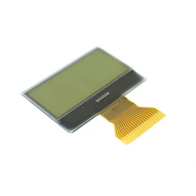
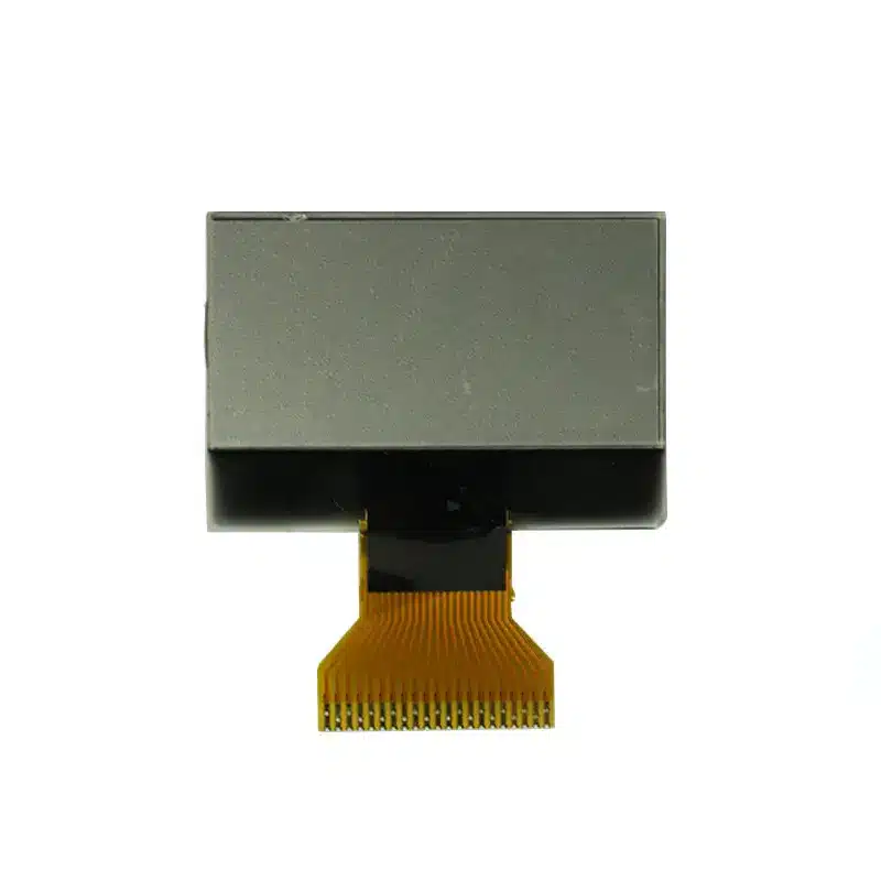
The Compact Audio Bar TFT LCD Module provides a narrow 2.9-inch visual area for products that need to display volume, source selection, track status, tuner information or compact equipment data without allocating space for a conventional rectangular screen.
Its native 320 × 120 pixel format uses a 70.08 × 26.28 mm active area within a 76.84 × 37.74 × 3.27 mm module. The TN, normally white, transmissive construction is designed around a defined 12-o’clock viewing direction, making installation orientation an important part of the enclosure design.
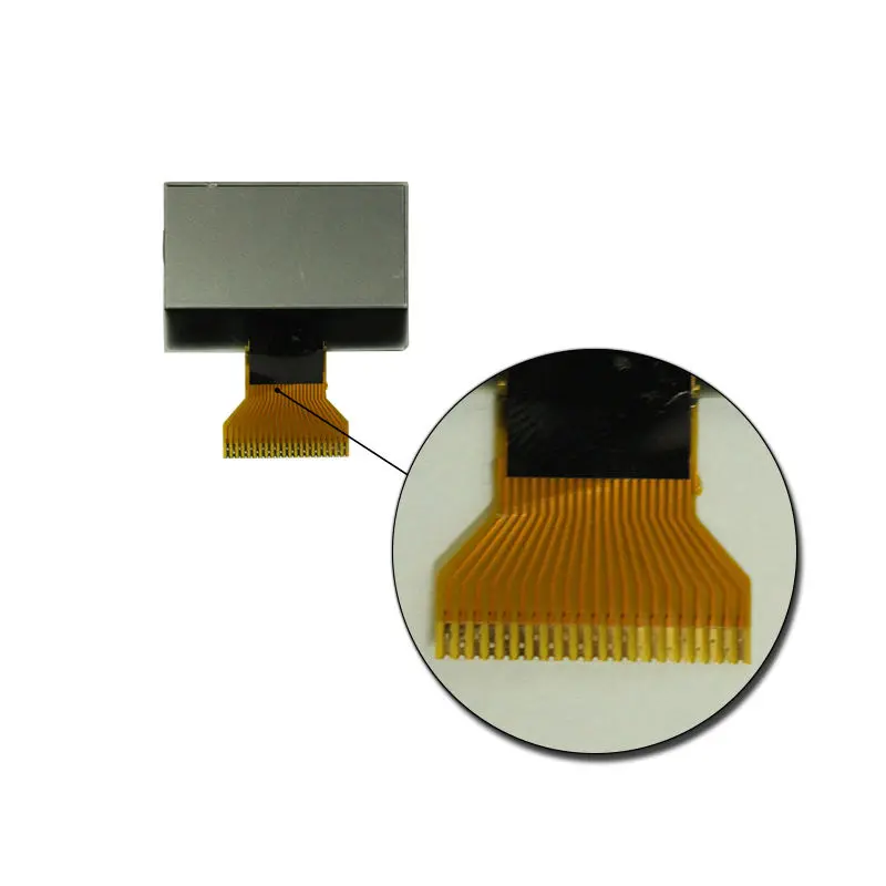
The module uses a 54-pin RGB FPC and is supplied without touch in its standard configuration. A complete RGB timing table, signal-voltage definition and pin map must be approved before the controller PCB is released.
Key Specifications
| Specification | Value |
|---|---|
| Display size | 2.9 inches |
| Resolution | 320 × 120 pixels |
| Display mode | TN, normally white, transmissive |
| Active area | 70.08 × 26.28 mm |
| Module outline | 76.84 × 37.74 × 3.27 mm |
| Luminance | 350 cd/m² typical |
| Contrast ratio | 400:1 typical |
| Response time | 50 ms typical |
| Pixel pitch | 0.219 × 0.219 mm |
| Viewing angle | 45/45/15/35° typical, U/D/L/R |
| Viewing direction | 12 o’clock |
| Interface | RGB, 54-pin FPC |
| Backlight | 6-chip WLED |
| Backlight reference | 19.8 V / 20 mA |
| Backlight lifetime | 30,000 hours typical |
| Operating temperature | −20°C to +70°C |
| Storage temperature | −30°C to +80°C |
| Touch | Non-touch standard configuration |
A 54-pin connector does not guarantee compatibility with another 54-pin RGB display.
Designing a 320 × 120 Audio Interface
Organize Information Along the Bar Format
The approximately 2.67:1 aspect ratio is suited to horizontal status information. Instead of adapting a full dashboard, the interface should use a limited number of clearly separated zones.
Possible arrangements include:
- source name on the left
- volume or frequency in the center
- play, pause or connection status on the right
- a horizontal equalizer or progress bar
- one-line alarm or operating message
- compact temperature, time or signal indicators
The 320-pixel width can support several short data fields, but the 120-pixel height requires disciplined typography and icon sizing.
Validate Text and Icon Legibility
Prototype artwork should be rendered directly at 320 × 120 pixels. Test:
- smallest label
- main numeric value
- track or station name
- thin progress bars
- muted and active icons
- warning symbols
- dark and light screen states
The 50 ms typical response time should be considered when designing rapidly moving animations. Static information, moderate transitions and status graphics are more representative qualification content than fast-scrolling visual effects.
54-Pin RGB Interface Qualification
Confirm Timing and Signal Mapping
An RGB interface requires the host to provide pixel data and timing signals continuously. The exact bus width, clock rate, synchronization mode, porches, signal polarity, voltage levels and pin positions must come from the controlled specification.
Comparable RGB TFT modules use separate color-data, clock, synchronization and data-enable signals, but their connector order and timing values can differ. A shared interface name or pin count is therefore insufficient for direct substitution.
Before schematic release, confirm:
- RGB bus width
- pixel-clock frequency
- HSYNC and VSYNC requirements
- data-enable operation
- horizontal and vertical timing
- signal polarity
- logic voltage
- panel power rails
- reset and control signals
- full 54-pin assignment
- FPC contact orientation
- connector mating model
The HX8238 is identified as the TFT driver IC. Its name alone does not establish host-side initialization, register programming or controller-board compatibility.
Match the Backlight Driver
The backlight is identified as a 6-chip WLED structure with a 19.8 V / 20 mA reference.
The host board should be checked for:
- required LED voltage range
- regulated current capability
- enable control
- dimming method, when required
- startup behavior
- protection limits
- thermal conditions
- connector and return-path arrangement
Do not connect the backlight directly from an unverified voltage rail.
Compact Audio Bar TFT LCD Module Mechanical Integration
Plan the Visible Opening
The confirmed active area is 70.08 × 26.28 mm. The visible enclosure opening should account for:
- active-image boundary
- bezel overlap
- black mask
- cover-lens border
- bonding or adhesive region
- FPC exit
- component keep-out
- connector clearance
The full module outline is 76.84 × 37.74 × 3.27 mm. The 3.27 mm figure describes the module thickness and does not include an unconfirmed custom cover, touch sensor or enclosure tolerance.
Align the 12-O’Clock Viewing Direction
The specified viewing performance is 45/45/15/35° typical in U/D/L/R order. This directional TN behavior means the installed orientation affects image appearance.
The 12-o’clock direction should face the intended viewing position defined by the equipment layout. A display rotated for mechanical convenience may produce poorer contrast or color appearance from the operator’s normal position.
The 12-o’clock viewing direction should be aligned with the installed user position.
Optical and Environmental Boundaries
The standard luminance is 350 cd/m² typical. This is suitable for evaluation in indoor and controlled-light products, but it does not establish direct-sunlight readability.
Finished visibility depends on:
- cover-lens transmission
- surface reflections
- air gap or bonding stack
- bezel shadow
- UI contrast
- ambient-light direction
- viewing orientation
- backlight operating point
The 350 cd/m² panel rating must be evaluated behind the final cover lens under target lighting.
The confirmed operating range is −20°C to +70°C, with storage from −30°C to +80°C. These values do not establish waterproofing, condensation resistance, shock resistance or automotive qualification.
Suitable Application Directions
Audio control panels
The bar format can display volume, source, track, tuner or connection information within a narrow front panel.
Tuners and receivers
The 320-pixel width can support frequency values, station identifiers, mode indicators and signal icons.
Speaker and amplifier interfaces
Compact audio products can use the display for input selection, gain settings, equalizer status and protection messages.
Appliance and equipment controls
The narrow active area can support status strips in products where a full-size HMI is unnecessary.
Instrument information strips
The module may be evaluated for single-line measurements, operating modes and alarm information within the confirmed temperature range.
Auxiliary operator displays
It may also support compact POS operator or kiosk status information, provided the host interface, lighting and enclosure are qualified. This wording does not imply payment certification.
Customization and Sample Review
Project-specific engineering review may cover:
- FPC length and direction
- 54-pin definition
- connector selection
- luminance target
- cover-lens size
- printed border
- AG, AR or AF surface treatment
- touch-panel addition
- air or optical bonding
- backlight requirements
- cable or controller-board matching
- branding
Touch is not included in the standard configuration. A touch version requires a separate sensor, controller, interface, cover construction and mechanical drawing.
Custom configurations are generally reviewed from 500 pieces, subject to tooling requirements, material availability and the requested specification. Sample and standard-module quantities are confirmed separately.
Procurement Checklist
Submit:
- host controller or processor
- required RGB bus width
- native 320 × 120 timing
- pixel-clock capability
- HSYNC, VSYNC and DE support
- full 54-pin assignment
- logic voltage
- panel power requirements
- backlight-driver capability
- connector preference
- FPC orientation
- normal viewing position
- enclosure opening
- cover-lens drawing
- touch requirement
- target lighting
- operating environment
- sample acceptance criteria
- annual demand
FAQ
About 2.9 Inch Compact Audio Bar TFT LCD Module
What must be checked before connecting the 54-pin RGB FPC?
How should audio data be arranged on a 320 × 120 display?
How does the 12-o’clock viewing direction affect installation?
Is 350 cd/m² sufficient behind a cover lens?
What does the HX8238 identifier establish?
When should an optional touch version be considered?
Freya Yang
+86 18318948097