Freya Yang
+86 18318948097
+852 62667476
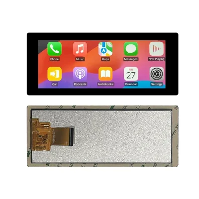
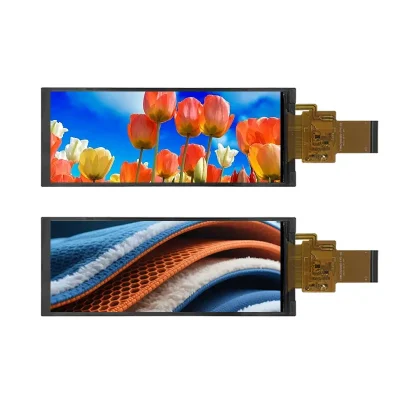
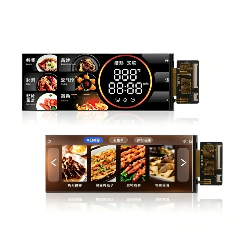
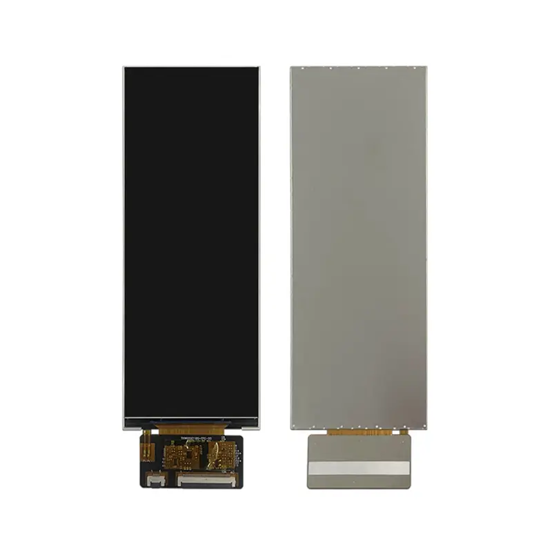
6.2 Inch Slim In-Cell Smart Equipment Touchscreen Module
Model P/N
Size
Resolution
Brightness
Viewing Angle
Connector Type
Operating Temp
Overall(mm)
huisoar
HS620011B0
Brand
Panel Size (inch)
Model P/N
Resolution
Brightness (nits)
Viewing Angle
Contrast Ratio
Response Time
Overall (mm)
Active Area (mm)
Refresh Rate
Display Colors
Panel Type
Connector Type
Operating Temp
Touchscreen Type
Storage Temp
Work Mode
Control Type
Operating Environment
Motherboard Type
Designed For
6.2 Inch Slim In-Cell Smart Equipment Touchscreen Module
The Slim In-Cell Smart Equipment Touchscreen Module combines a 480 × 1280 IPS screen, 1200 cd/m² luminance and an ultra-thin 2.23 mm structure for portrait control interfaces.
Product Summary
The Slim In-Cell Smart Equipment Touchscreen Module provides a narrow interactive display area for equipment menus, operating status, settings and alerts. Its portrait geometry supports products that have limited installation width but still require a detailed graphical interface and direct touch input.
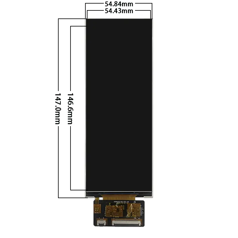
The 6.2-inch display has a 54.43 × 146.65 mm active area within a 54.84 × 147.05 × 2.23 mm outline. It combines IPS viewing, 1200 cd/m² typical luminance, a 1200:1 typical contrast ratio, In-Cell touch and a 40-pin CPU/RGB display connection.
Key Specifications
| Parameter | Value |
|---|---|
| Display size | 6.2 inch |
| Resolution | 480 × 1280 pixels |
| Format | Portrait bar, approximately 3:8 |
| Panel type | IPS a-Si TFT-LCD |
| Touch construction | In-Cell touch |
| Optical structure | Transmissive |
| Luminance | 1200 cd/m² typical |
| Contrast ratio | 1200:1 typical |
| Viewing angle | 80/80/80/80, L/R/U/D |
| Display colors | 16.7M |
| Interface | 40-pin CPU/RGB |
| Active area | 54.43 × 146.65 mm |
| Overall size | 54.84 × 147.05 × 2.23 mm |
| Backlight | WLED |
| Operating temperature | −20°C to +70°C |
| Storage temperature | −30°C to +80°C |
Native 480 × 1280 Portrait Interface Design
Vertical Menu and Touch Zones
The native raster supports information arranged in a top-to-bottom sequence. A portrait user interface can divide the screen into areas for:
- operating mode
- temperature or timing
- equipment status
- function selection
- warning messages
- process progress
- media controls
- maintenance prompts
- confirmation buttons
- navigation menus
The narrow format can fit into equipment doors, appliance fascias, side-control areas and compact instrument housings where a landscape display would consume excessive width.
Native-Raster Software Preparation
The interface should be created directly for the native 480 × 1280 raster.
Before software approval, verify:
- portrait orientation
- native RGB timing
- font size
- icon dimensions
- touch-target spacing
- menu hierarchy
- alert placement
- safe margins
- language expansion
- boot-screen layout
Rotating an existing landscape interface without redesign may result in inefficient spacing, small touch targets or inconsistent navigation.
High-Luminance IPS Optical Performance
1200 cd/m² Panel Luminance Boundary
The panel is specified at 1200 cd/m² typical luminance. This provides a strong optical starting point for equipment installed under bright indoor lighting or in higher-ambient-light locations.
A 1200 cd/m² panel does not by itself establish finished-system sunlight readability.
Final visibility depends on:
- cover-lens transmission
- surface reflectance
- air-gap construction
- optical bonding
- viewing angle
- installation position
- direct illumination
- enclosure shading
- thermal conditions
Representative samples should be tested with the intended cover lens and enclosure.
Viewing Angle, Contrast and Color
The display provides 80/80/80/80 viewing angles in the left, right, upper and lower directions. This supports panels viewed while standing, operating from the side or approaching from different positions.
The 1200:1 typical contrast ratio supports separation between backgrounds, menu text, food images, operating values and alert graphics. The 16.7M-color capability supports graphical interfaces, but it does not establish calibrated color accuracy or a particular color gamut.
40-Pin CPU/RGB Host Integration
Bus Width, Timing and Pinout Qualification
A 40-pin CPU/RGB connector does not guarantee bus-width, timing, voltage or pin compatibility with another panel.
Before designing the host board or FPC, confirm:
- CPU or RGB operating route
- RGB bus width
- pixel format
- pixel-clock frequency
- horizontal timing
- vertical timing
- sync polarities
- data-enable behavior
- complete 40-pin assignment
- connector pitch
- contact side
- FPC orientation
- panel logic voltage
- backlight voltage and current
- backlight enable and dimming
Another 6.2-inch 480 × 1280 panel may use MIPI or a different RGB definition, so size and resolution alone do not establish interchangeability.
Non-RGB Hosts Require Conversion
A native HDMI, USB, LVDS, eDP or MIPI DSI source cannot be assumed to connect directly to this CPU/RGB panel.
A suitable controller or bridge must provide:
- the required parallel display signals
- correct native timing
- voltage-compatible I/O
- panel power
- backlight control
- the required touch-control path
Controller qualification should take place before PCB release.
In-Cell Touch Integration Requirements
Touch Protocol and Controller Confirmation
In-Cell touch is confirmed, but the touch communication protocol and controller reference are not established.
Before firmware or PCB work, confirm:
- touch communication interface
- touch-controller identity
- touch voltage
- interrupt and reset signals
- connector sharing or separation
- touch-point count
- coordinate orientation
- firmware version
- noise requirements
- wake and sleep behavior
The display’s 40-pin CPU/RGB connection does not prove that all touch signals share the same connector.
Touch Firmware and Cover-Lens Validation
Touch performance should be qualified with the intended front stack.
Review:
- cover-lens material
- lens thickness
- printed border
- bonding method
- air gap
- grounding
- charger and motor noise
- wet-finger behavior
- glove requirements
- edge sensitivity
- coordinate mapping
An In-Cell structure can reduce the need for a separate external touch sensor layer, but the final stack and firmware still require project-specific validation.
Slim In-Cell Smart Equipment Touchscreen Module Mechanics
Active Area and Front Opening
The active image area measures 54.43 × 146.65 mm. This value should guide:
- visible front opening
- cover-lens window
- printed black mask
- panel alignment
- interface-safe margins
- touch-target placement
- alert visibility
Critical controls should remain inside the approved visible and touchable area after bezel overlap and manufacturing tolerances are applied.
Ultra-Thin Outline and FPC Clearance
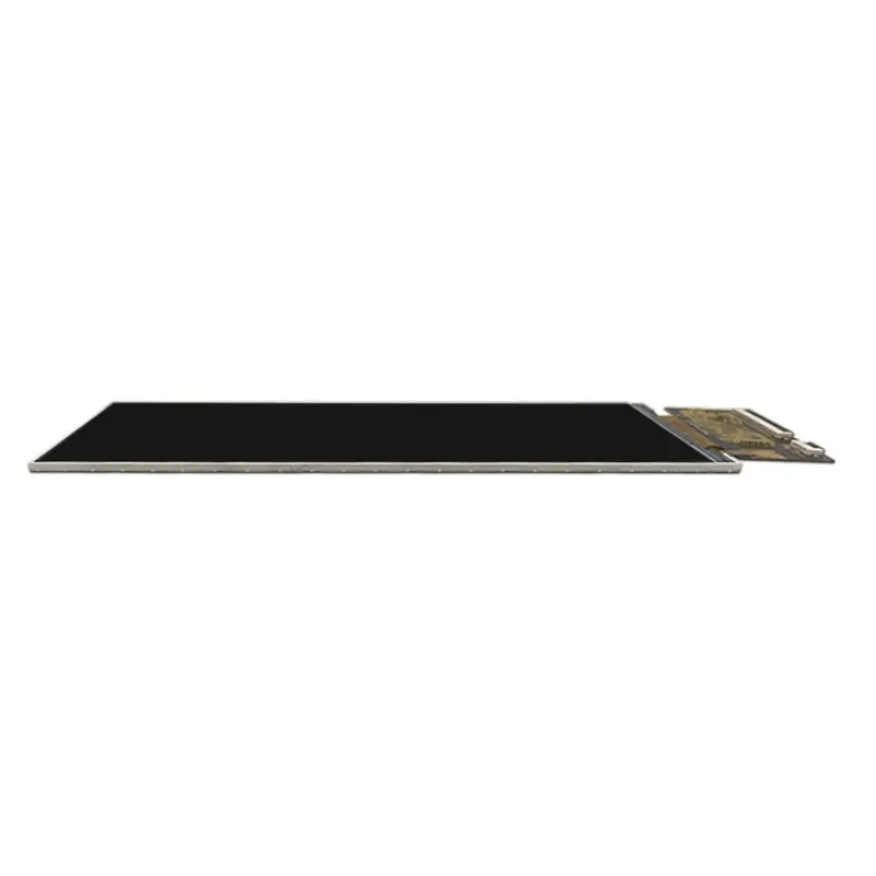
The complete module measures 54.84 × 147.05 × 2.23 mm.
Mechanical review should include:
- module outline
- active-area position
- FPC exit
- connector position
- cable bend radius
- rear clearance
- mounting pressure
- cover-lens overlap
- adhesive thickness
- enclosure tolerances
- service access
The 2.23 mm thickness supports slim product structures, but it does not include unspecified housing, controller-board or external cover-lens thickness.
Application Integration
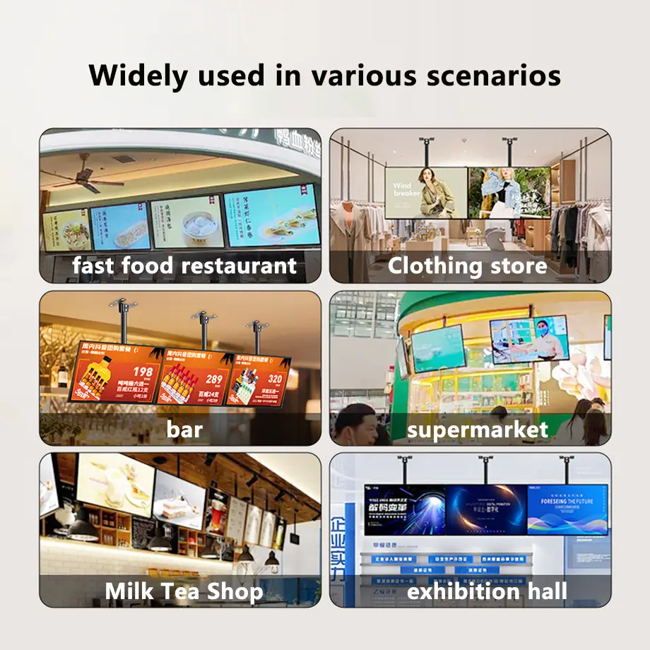
Industrial Equipment Displays
The portrait touchscreen can present machine status, operating modes, alarms, setpoints and maintenance prompts in industrial equipment. The host and touch system must be qualified for the final electrical-noise, grounding and operating environment.
Medical Instrument Displays
The module can be evaluated as a user-interface component for medical instruments that require a narrow touchscreen area. Product-level medical certification, risk management, electrical safety, cleaning resistance and regulatory compliance remain responsibilities of the finished-equipment program.
Range Hood and Oven Displays
The narrow format supports range hood and oven interfaces with vertically arranged fan settings, temperatures, timers, cooking modes and maintenance alerts. Final qualification should account for heat, steam, grease, cleaning agents and front-glass construction.
Smart Speaker Displays
Smart speakers can use the portrait touchscreen for media status, volume, connectivity, voice-assistant feedback, timers and menu controls. Acoustic vibration, enclosure grounding and touch-noise behavior should be assessed in the complete assembly.
Temperature Qualification
The display is specified for operation from −20°C to +70°C and storage from −30°C to +80°C.
These limits support evaluation across the stated application fields, but they do not independently establish compliance with a particular industrial, appliance or medical standard.
System tests should include:
- cold startup
- high-temperature image behavior
- touch response across temperature
- backlight output
- controller temperature
- enclosure heat
- condensation
- repeated thermal cycling
- electrical-noise immunity
- cleaning exposure where relevant
Testing should use the final host, touch firmware, cover lens and enclosure.
Custom Integration Options
Project review may include:
- CPU/RGB host matching
- custom 40-pin FPC
- native timing verification
- touch-controller and protocol qualification
- touch firmware
- cover-lens sizing
- anti-glare or anti-reflection treatment
- optical bonding
- enclosure adaptation
- FPC routing
- branding
- packaging and labeling
Custom configurations are generally reviewed from 500 pieces, subject to tooling requirements, material availability and the requested specification. Sample and standard-module quantities are confirmed separately.
Customization for the Slim In-Cell Smart Equipment Touchscreen Module should begin only after the complete display, touch and mechanical documents are approved.
Procurement Checklist
Before requesting samples or approving production, submit or confirm:
- native 480 × 1280 timing
- CPU/RGB operating route
- RGB bus width and pixel format
- pixel-clock and sync requirements
- complete 40-pin assignment
- panel logic voltage
- backlight voltage and current
- backlight enable and dimming
- touch protocol and controller
- touch firmware and point count
- touch reset and interrupt signals
- connector pitch
- contact side and FPC orientation
- 54.84 × 147.05 × 2.23 mm enclosure fit
- 54.43 × 146.65 mm active-area position
- cover-lens construction
- 1200 cd/m² lighting target
- operating-temperature requirements
- intended application field
- sample quantity
- annual demand
- production schedule
Sample approval should precede controller release, FPC manufacture, cover-lens tooling and enclosure production.
FAQ
About Slim In-Cell Smart Equipment Touchscreen Module
What must be checked before connecting a 40-pin CPU/RGB host?
How should the portrait UI and touch targets be prepared?
Does 1200 cd/m² guarantee sunlight readability?
What must be confirmed for the In-Cell touch path?
What does the JD9265T identifier establish?
Freya Yang
+86 18318948097