
Freya Yang
+86 18318948097
+852 62667476
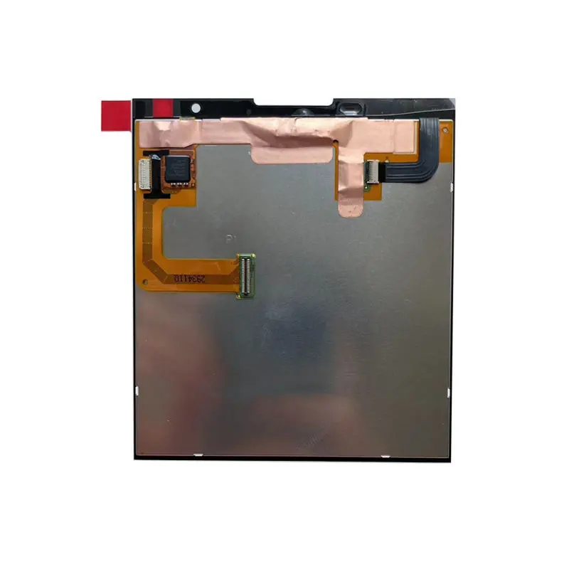
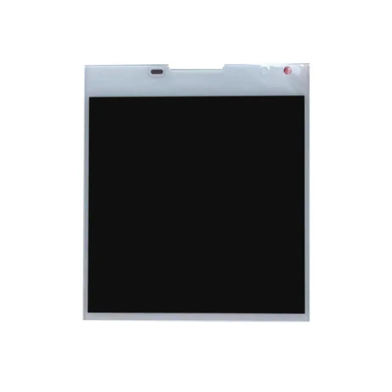
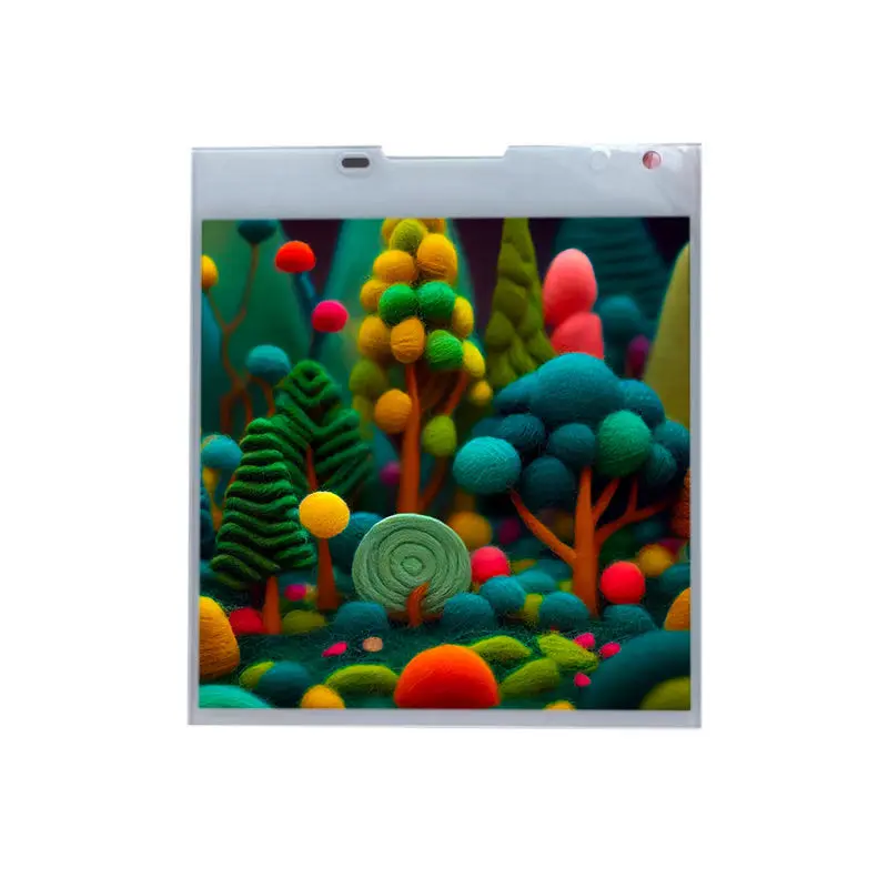
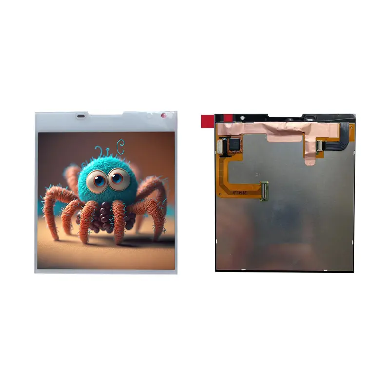
4.5 Inch Square TFT Display Module for Smart Control Panels
Model P/N
Size
Resolution
Brightness
Viewing Angle
Connector Type
Operating Temp
Overall(mm)
huisoar
HS45AA12A-V1
Brand
Panel Size (inch)
Model P/N
Resolution
Brightness (nits)
Viewing Angle
Contrast Ratio
Response Time
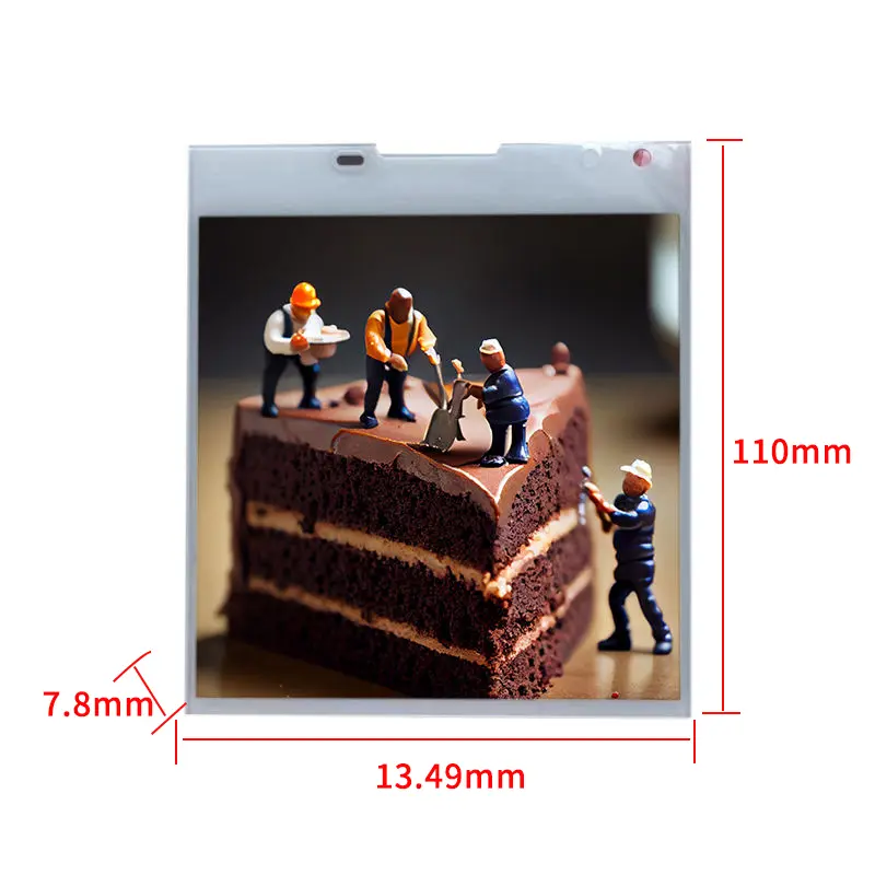
Overall (mm)
Active Area (mm)
Refresh Rate
Display Colors
Panel Type
Connector Type
Operating Temp
Touchscreen Type
Storage Temp
Work Mode
Pixel Format
Designed For
4.5 Inch Square TFT Display Module for Smart Control Panels
This high-resolution square IPS module combines a native 1440 × 1440 canvas, 800 cd/m² typical luminance and MIPI connectivity for compact embedded interfaces.
Product Summary
The Square TFT Display Module provides a 4.5-inch, 1:1 visual area for equipment that requires a balanced interface rather than a conventional widescreen layout. Its native 1440 × 1440 resolution supports detailed icons, circular controls, charts, camera views and information grids within a square user-interface zone.
The confirmed active area measures 105.52 × 105.52 mm. IPS panel technology and 800 cd/m² typical luminance provide a strong basis for clear graphics in controlled indoor and high-ambient-light installations. Final optical performance must still be evaluated through the intended cover lens and enclosure.
The display uses a MIPI interface and identifies the R69433 component. Host compatibility must be established from the complete interface specification, including lane configuration, timing, voltage, pin assignment and required command documentation.
Key Specifications
| Specification | Value |
|---|---|
| Display size | 4.5 inches |
| Native resolution | 1440 × 1440 pixels |
| Aspect ratio | 1:1 |
| Panel technology | IPS TFT LCD |
| Active area | 105.52 × 105.52 mm |
| Luminance | 800 cd/m² typical |
| Interface | MIPI |
| Pixel arrangement | RGB stripe |
| Driver identifier | R69433 |
| Operating temperature | −20°C to +60°C |
| Storage temperature | −30°C to +70°C |
A shared resolution or MIPI label does not make two display modules interchangeable. Electrical, command, timing and mechanical requirements must all match.
Native 1440 × 1440 Interface Design
Build the UI for a 1:1 Canvas
The native square format should be treated as the starting point for the interface design. Adapting a widescreen layout can leave unused areas, distort graphics or force text into inefficient arrangements.
Useful square layouts include:
- central status dial with surrounding controls
- four-quadrant control menu
- camera image with edge-mounted status indicators
- equipment diagram with alarm zones
- circular thermostat or scene controller
- balanced measurement dashboard
- square product-selection interface
Artwork should be prepared directly at 1440 × 1440 pixels. This avoids unnecessary scaling and allows the display’s native pixel matrix to present text, line graphics and icons accurately.
Validate Text and Graphics at Native Resolution
High pixel count does not automatically guarantee readable text. Font size must be selected according to the 105.52 mm active-area width, expected viewing distance and final cover construction.
Prototype content should include:
- smallest operating label
- numeric readout
- warning text
- thin graphical lines
- icon borders
- gradients
- camera or image content
- primary and secondary colors
Testing should use the final rendering engine and intended MIPI host rather than a rescaled screenshot.
MIPI Host Integration
Confirm Lane, Timing and Command Requirements
MIPI describes the interface family, but the label does not establish the complete connection.
Before electrical design, obtain:
- MIPI DSI lane count
- lane speed
- command or video mode
- pixel format
- refresh rate
- horizontal timing
- vertical timing
- clock requirements
- logic and panel voltages
- reset requirements
- connector drawing
- complete pin assignment
- initialization command documentation
- power sequence
- backlight requirements
High-resolution square displays can require a substantial data path. Comparable 1440 × 1440 MIPI modules are specified with detailed lane, connector and timing configurations, confirming that these fields must be verified for the exact panel rather than inferred from resolution alone.
Treat the R69433 as an Identifier
The R69433 designation may be recorded as a component identifier, but it does not by itself establish:
- its exact function in the module
- the initialization sequence
- host-side register requirements
- supported MIPI mode
- lane count
- power sequence
- software compatibility
Engineering approval must rely on the controlled interface documentation for the exact module.
Square TFT Display Module Mechanical Planning
Use the Active Area for the Visible Opening
The confirmed image area is 105.52 × 105.52 mm. This dimension should guide the minimum visible window and user-interface placement.
The front-panel design should distinguish among:
- active image area
- visible opening
- black mask
- cover-lens border
- module outline
- FPC route
- connector clearance
- mechanical supports
- adhesive or bonding area
Controls placed too close to the edge may be obscured by the bezel or cover-lens printing.
Obtain the Controlled Outline Drawing
The provided exact-product table contains an internally unclear module-size entry. Enclosure tooling should therefore not be released from that text value.
Request a controlled drawing showing:
- full width and height
- total thickness
- active-area position
- datum points
- corner geometry
- FPC location
- FPC length
- connector position
- component keep-out areas
- mounting and bonding tolerances
The mechanical drawing should be approved before cover glass, housing or PCB positions are frozen.
Optical and Environmental Boundaries
The standard luminance is 800 cd/m² typical. This value can support visibility in many bright indoor environments, but it does not by itself establish direct-sunlight readability.
Finished-system visibility depends on:
- cover-lens transmission
- surface reflections
- air or optical bonding
- viewing direction
- ambient-light angle
- UI contrast
- image content
- enclosure shading
Evaluate a complete sample under the actual lighting conditions.
The confirmed operating range is −20°C to +60°C, with storage from −30°C to +70°C. These values do not establish waterproofing, condensation resistance, automotive grade or medical certification.
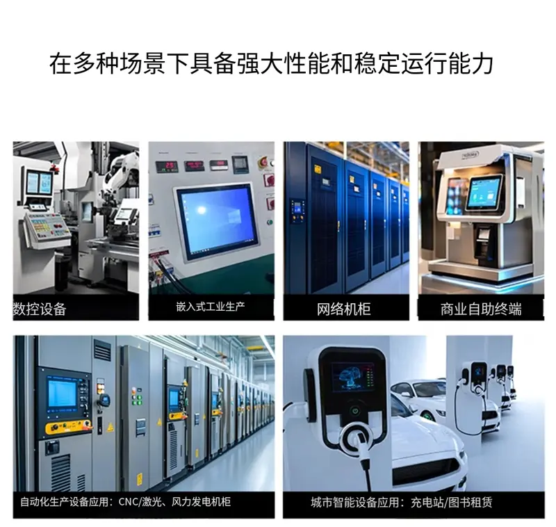
Suitable Application Directions
Smart control panels
The 1:1 canvas supports balanced touch-style or button-driven interfaces for lighting, climate and room-control products. Touch functionality must be separately defined if required.
Industrial instruments
Detailed square graphics can support measurement dashboards, alarm indicators and machine-status interfaces in equipment that operates within the confirmed temperature range.
Smart-home hubs
A square display can present scene selection, environmental values, security status and connected-device controls within a compact wall-mounted product.
Embedded terminals
The module may be evaluated for compact terminals where enclosure geometry favors a square visual opening and the host processor has an appropriate MIPI interface.
Specialized imaging interfaces
The 1440 × 1440 matrix can support detailed camera, inspection or image-based interfaces. System suitability depends on refresh rate, rendering performance and the complete MIPI configuration.
Customization and Sample Review
Project-specific feasibility review may cover:
- cover-lens dimensions
- printed border
- AG, AR or AF surface treatment
- optical bonding
- touch integration
- FPC direction and length
- connector orientation
- luminance target
- mechanical frame
- branding
- cable and host-board matching
These features are not treated as standard unless confirmed in the approved specification.
Custom configurations are generally reviewed from 500 pieces, subject to tooling requirements, material availability and the requested specification. Sample and standard-module quantities are confirmed separately.
Procurement Checklist
Submit the following before sample connection:
- host processor or SoC
- available MIPI DSI ports
- supported lane count
- required refresh rate
- native 1440 × 1440 timing
- command or video mode requirements
- connector and pinout
- logic and panel voltages
- initialization documents
- power-sequence requirements
- enclosure opening
- controlled outline drawing
- FPC routing
- cover-lens construction
- touch requirement
- ambient-light conditions
- operating-temperature range
- sample acceptance criteria
- forecast quantity
FAQ
About 4.5 Inch Square TFT Display Module
What must be checked before connecting the module to a MIPI host?
How should a square UI be prepared for this display?
Is 800 cd/m² sufficient for a bright installation?
Which dimensions should be used for enclosure tooling?
Does the R69433 identifier define the initialization procedure?
Is touch included in the standard module?
Freya Yang
+86 18318948097
