
Freya Yang
+86 18318948097
+852 62667476
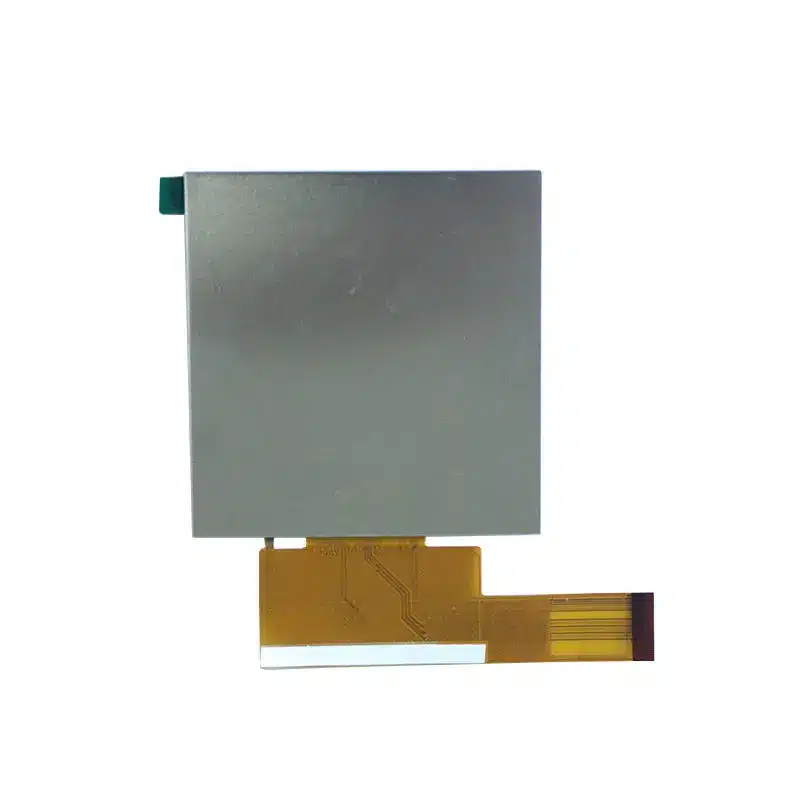
3.95 Inch Lighting Control LCD Module for Smart Wall Panels
Model P/N
Size
Resolution
Brightness
Viewing Angle
Connector Type
Operating Temp
Overall(mm)
huisoar
HS0395SVN-01
Brand
Panel Size (inch)
Model P/N
Resolution
Brightness (nits)
Viewing Angle
Contrast Ratio
Response Time
Overall (mm)
Active Area (mm)
Refresh Rate
Display Colors
Panel Type
Connector Type
Operating Temp
Touchscreen Type
Storage Temp
Work Mode
Pixel Format
Control Type
Operating Environment
Designed For
3.95 Inch Lighting Control LCD Module for Smart Wall Panels
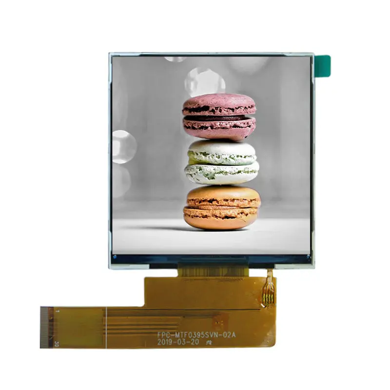
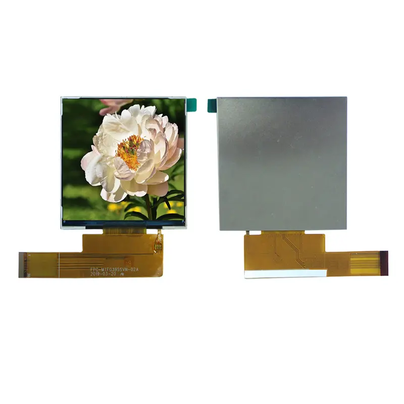
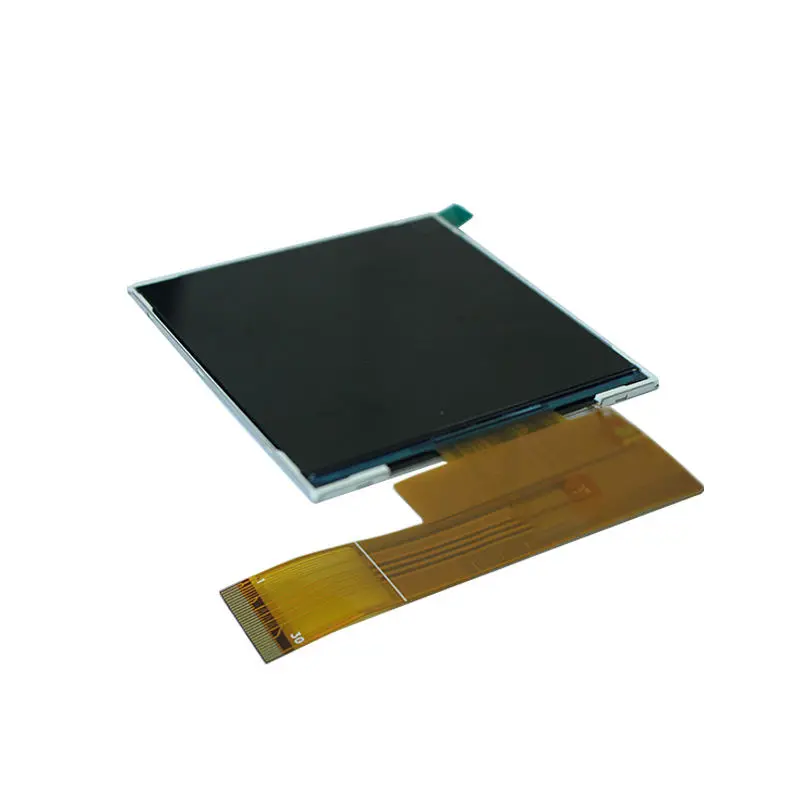
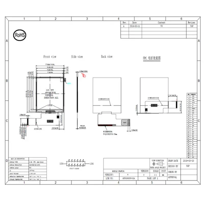
This compact Lighting Control LCD Module provides a square 480 × 480 interface area for lighting scenes, dimming levels, color-temperature controls and equipment status. Its 3.95-inch TFT format uses a 70.18 × 70.18 mm active area within a 77 × 80 × 2.30 mm outline, supporting integration into wall-mounted controllers and compact embedded panels.
The standard configuration delivers 350 cd/m² luminance and is intended primarily for indoor or controlled-light installations. An RGB display path connects the panel to a compatible embedded host, subject to confirmation of timing, voltage levels, control signals and the complete FPC assignment.
Product Summary
The square format gives interface designers equal horizontal and vertical working space. This is useful for circular dimmer graphics, four-quadrant scene controls, color-selection tools, status icons and centered numeric readouts.
The module is a display component rather than a finished smart switch. A host processor, suitable RGB signal generation, backlight driving and the final mechanical enclosure remain part of the customer’s system design.
A square 480 × 480 canvas supports balanced control layouts without adapting a conventional wide-screen interface.
Key Specifications at a Glance
| Specification | Confirmed value |
|---|---|
| Display size | 3.95 inches |
| Resolution | 480 × 480 pixels |
| Display technology | TFT LCD |
| Shape | Square |
| Active area | 70.18 × 70.18 mm |
| Module outline | 77 × 80 × 2.30 mm |
| Luminance | 350 cd/m² |
| Viewing characteristic | Full-viewing designation |
| Display interface | RGB |
| Driver IC identifier | ST7701S |
| Operating temperature | −20°C to +70°C |
| Touch configuration | Non-touch standard module |
Square 480 × 480 Interface Design
Balanced UI Space for Lighting Scenes
The 1:1 pixel layout supports symmetrical controls without leaving the unused side margins common when wide-screen content is placed inside a square enclosure. Designers can arrange scene presets around a central control, divide the display into equal status regions or present vertically and horizontally balanced menus.
Native 480 × 480 artwork should be prepared for the final interface. Scaling graphics from a rectangular source can distort icons and reduce text clarity.
Full-Viewing Installation Flexibility
The full-viewing designation supports panels that may be observed from different standing positions. This is valuable for wall controls installed above, below or beside the user’s normal line of sight.
The exact numerical viewing-angle test conditions are not confirmed, so the final cover lens, mounting angle and interface colors should be checked with a physical sample.
RGB Integration for the Lighting Control LCD Module
The Lighting Control LCD Module uses an RGB display route rather than a finished HDMI, USB, MIPI DSI, eDP or LVDS input. The host must generate the required pixel clock, synchronization and pixel-data signals defined by the approved module specification.
Timing, Voltage and Pin-Mapping Checks
A connector with the expected number of contacts does not guarantee electrical compatibility. Engineering approval should compare:
- complete FPC pin assignment
- RGB data format
- pixel-clock requirements
- horizontal and vertical timing
- data-enable and synchronization use
- logic-voltage levels
- reset and control signals
- backlight electrical requirements
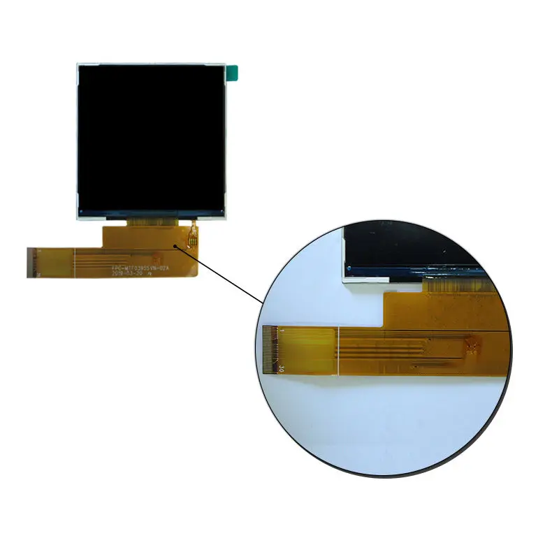
- FPC contact side and insertion direction
An RGB interface label does not establish compatibility without timing, voltage and pin-map confirmation.
Hosts that provide HDMI, LVDS, eDP or MIPI DSI require an appropriate conversion or display-controller stage rather than a direct cable connection.
ST7701S Identification Boundary
ST7701S is identified in the product information as the display driver IC. The identifier alone does not establish a particular host initialization sequence, register table, power sequence or firmware requirement.
Those requirements must be taken from the approved module documentation for the production configuration.
Mechanical Integration into Smart Wall Panels
Active Area and Enclosure Opening
The visible image area measures 70.18 × 70.18 mm, while the module outline measures 77 × 80 × 2.30 mm. The difference between these dimensions must be reflected in the bezel and support structure.
The enclosure review should account for:
- bezel overlap around the active image
- FPC exit direction and bend radius
- connector insertion clearance
- backlight and controller-board space
- adhesive or mounting support
- cover-lens thickness
- tolerance accumulation
- service and assembly access
A square front opening should be dimensioned from the approved drawing rather than only from the nominal 3.95-inch diagonal.
Optical and Environmental Boundaries
The standard luminance is 350 cd/m². This level suits many indoor wall panels, room controls and equipment interfaces, but readability will also depend on the cover material, reflections, ambient illumination and UI contrast.
The 350 cd/m² panel rating is intended for indoor or controlled-light installations and does not establish sunlight readability.
The listed operating range is −20°C to +70°C. Finished-device qualification still needs to consider enclosure heat, backlight temperature, host-board dissipation, condensation risk and the actual duty cycle.
Recommended Applications
The module may be evaluated for:
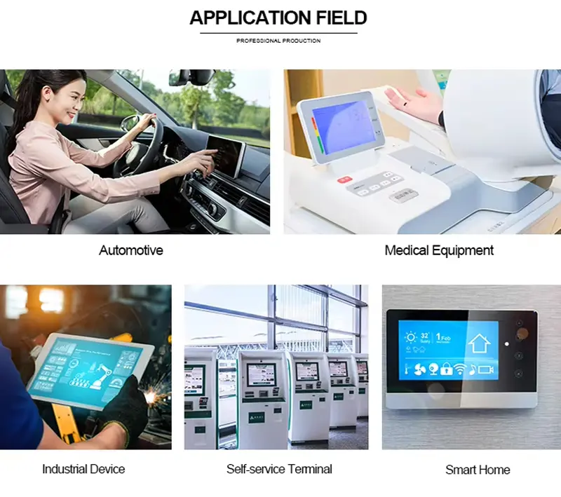
- smart lighting wall panels
- dimmer and scene-selection controls
- color-temperature controllers
- building-automation interfaces
- room-control systems
- compact smart-home hubs
- appliance status panels
- embedded equipment controls
No finished-device certification, ingress-protection rating, touch functionality or direct compatibility with a particular processor platform is implied.
Customization and Sample Qualification
The square display can be evaluated with project-specific changes such as FPC length or orientation, connector mapping, cover-lens geometry, printing, surface treatment, bonding stack, backlight target and branding.
Custom configurations are generally reviewed from 500 pieces, subject to tooling requirements, material availability and the requested specification. Sample and standard-module quantities are confirmed separately.
A standard sample should be approved before production tooling or enclosure release. The sample review should include native image output, color order, viewing orientation, startup behavior, backlight operation, FPC handling and mechanical fit.
Procurement Checklist
Submit the following for an engineering review:
- host processor or display-controller model
- complete RGB timing specification
- proposed FPC pin assignment
- signal-voltage requirements
- backlight-driver information
- FPC contact side and orientation
- enclosure and bezel drawing
- cover-lens specification
- ambient-light target
- operating-temperature requirements
- sample quantity
- estimated annual demand
FAQ
About 3.95 Inch Lighting Control LCD Module
What must be checked before replacing another 480 × 480 square LCD?
Can this display connect directly to an HDMI or MIPI DSI host?
How should 350 cd/m² be evaluated behind a cover lens?
Does the ST7701S identifier define the required initialization code?
What information is needed to customize the FPC or cover lens?
Freya Yang
+86 18318948097
