Freya Yang
+86 18318948097
+852 62667476
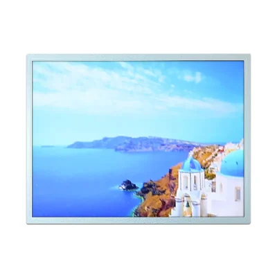
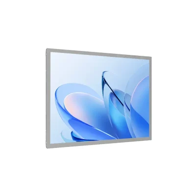
15 Inch CCFL XGA Industrial Control LCD Module for HMI
Model P/N
Size
Resolution
Brightness
Viewing Angle
Connector Type
Operating Temp
Overall(mm)
huisoar
HS150HD-R035
Brand
Panel Size (inch)
Model P/N
Resolution
Brightness (nits)
Viewing Angle
Contrast Ratio
Response Time
Overall (mm)
Active Area (mm)
Refresh Rate
Display Colors
Panel Type
Connector Type
Surface Treatment
Operating Temp
Touchscreen Type
Storage Temp
Work Mode
Pixel Format
Input Voltage (V)
Weight (g)
Operating Environment
I/O Interface
Designed For
15 Inch CCFL XGA Industrial Control LCD Module for HMI
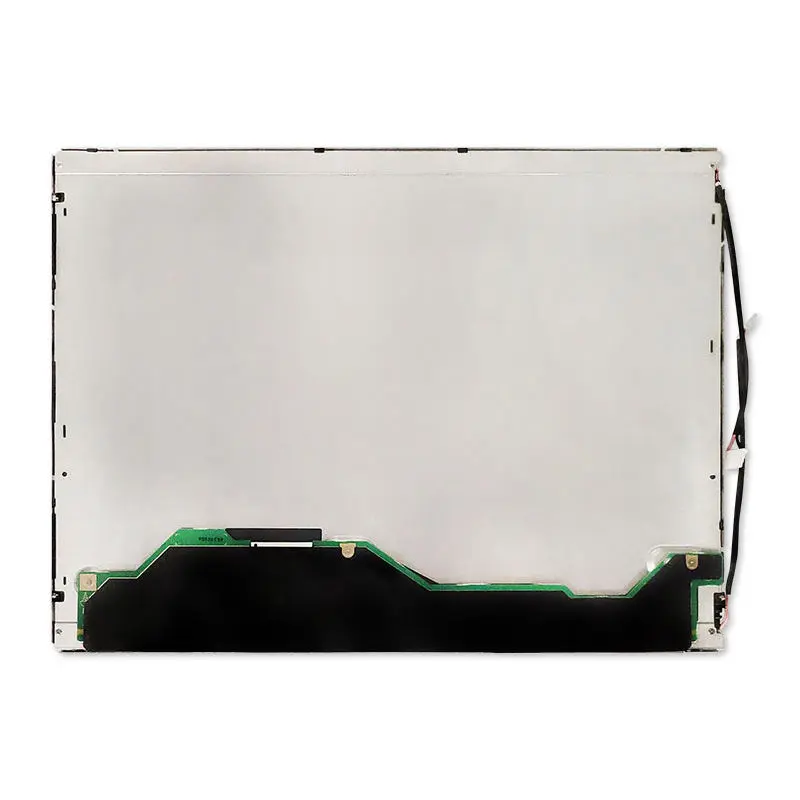
A 15-inch 4:3 display remains useful when an industrial interface is built around XGA graphics, fixed enclosure dimensions, and LVDS. This CCFL XGA Industrial Control LCD Module combines 1024 × 768 resolution, 350 cd/m² typical luminance, anti-glare 3H treatment, a 20-pin one-channel 8-bit LVDS interface, and dual-CCFL backlighting. Its TN normally-white transmissive construction and 6-o’clock view direction make mounting orientation an important part of integration.
Product Summary
4:3 XGA Layout for Established Control Interfaces
The 1024 × 768 raster provides a 4:3 workspace for operator menus, status graphics, trend windows, alarm pages, and equipment-control screens. For systems already designed around XGA, using the native raster preserves intended UI proportions. The active image area is 304.128 × 228.096 mm.
350 cd/m² with Anti-Glare 3H Surface
The module provides 350 cd/m² typical luminance and a 550:1 typical contrast ratio. Its front treatment is anti-glare with 25% haze and a 3H hard coating. This configuration fits controlled indoor industrial lighting; it should not be positioned as a direct-sun display.
Key Specifications
| Parameter | Specification |
|---|---|
| Display size | 15 inches |
| Resolution | 1024 × 768 pixels, XGA |
| Panel structure | a-Si TFT-LCD, LCM |
| Operating mode | TN, normally white, transmissive |
| Active area | 304.128 × 228.096 mm |
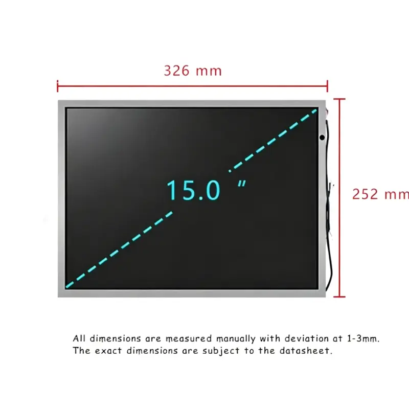
| Module outline | 326 × 252 × 11.7 mm |
| Brightness | 350 cd/m² typical |
| Contrast ratio | 550:1 typical |
| View direction | 6 o’clock |
| Viewing-angle sequence | 60°/60°/45°/55° typical at CR ≥ 10; direction order to confirm |
| Response time | 2 ms / 6 ms typical, Tr/Td |
| Display colors | 16.2M |
| Refresh rate | 60 Hz |
| Surface | Anti-glare, 25% haze, 3H hard coating |
| LCD interface | LVDS, 1 channel, 8-bit, 20 pins |
| Panel input | 3.3 V typical |
| Backlight | 2 × CCFL, 50,000-hour reference, without driver |
| Maximum mass | 1,000 g |
| Operating temperature | 0°C to +60°C |
| Storage temperature | −25°C to +60°C |
| Touch | Ordered option; exact configuration to confirm |
Planning 1024 × 768 HMI Content
Drive the Native XGA Raster When Practical
Native 1024 × 768 content avoids unnecessary resampling and helps preserve the geometry of buttons, labels, trend charts, and legacy interfaces. A controller should be qualified for the required XGA timing rather than selected only because it has an LVDS connector.
Validate Optics in the Finished Equipment
The 350 cd/m² rating describes the panel, not final visibility behind a cover lens. Front-window transmission, reflections, ambient light, and viewing distance should be included in qualification. Anti-glare treatment can reduce reflection, but it does not establish outdoor or sunlight-readable performance.
Integrating the CCFL XGA Industrial Control LCD Module
Qualify the 20-Pin LVDS Host Connection
The native video interface is 20-pin LVDS using one channel and 8-bit signaling. A matching connector does not prove compatibility. Approval should cover native timing, full pin assignment, bit mapping, connector orientation, cable routing, voltage, and control signals.
The panel logic input is 3.3 V typical. It is not the complete display-system power requirement.
Plan a Separate Dual-CCFL Inverter Path
The backlight uses two CCFL lamps and is specified without a driver. An external inverter or backlight driver matched to the ordered lamp configuration is therefore required.
Panel logic power and CCFL power are separate paths. Confirm lamp connectors, electrical requirements, inverter controls, and enclosure clearance before design release.
TN Optical Behavior and Mounting Orientation
Use the 6-O’Clock View Direction During Mechanical Planning
The TN panel is normally white and transmissive, with a confirmed 6-o’clock view direction. Compare that direction with the normal operator eye position before fixing LCD rotation.
The viewing data is a raw 60°/60°/45°/55° sequence at CR ≥ 10. Do not assign the four numbers to directions until the ordered production specification confirms the order.
Response and Color Characteristics
The module specifies 2 ms / 6 ms typical Tr/Td response, 16.2M colors, RGB vertical stripe arrangement, and 60 Hz refresh. These values provide a clear baseline for menu-driven industrial interfaces and status graphics.
Mechanical Fit for Equipment Replacement
Separate Active Area from the Module Envelope
The 304.128 × 228.096 mm active area defines the illuminated region, while the 326 × 252 × 11.7 mm outline determines physical clearance. Maximum mass is 1,000 g.
Replacement projects should also check mounting locations, connector position, lamp leads, cable bend space, and dimensional tolerances. Matching nominal size and resolution do not guarantee mechanical interchangeability.
Optional Touch and Controller-Board Boundaries
Specify Touch as an Ordered Configuration
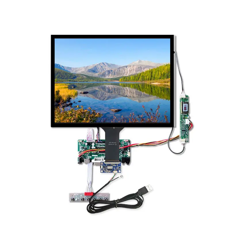
Touch should be treated as order-specific. If capacitive touch is required, confirm the touch controller, interface, voltage, point count, cover-lens stack, FPC routing, firmware, and finished thickness. The LVDS video interface does not define the touch-control interface.
Keep Controller-Board Functions Separate from Native Panel I/O
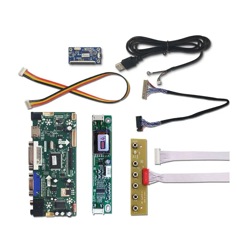
External boards may provide VGA, HDMI-compatible, USB, or other inputs, but those ports are not native interfaces of the LCD. Native display input remains the specified 20-pin LVDS path. Controller inclusion, firmware, cables, and I/O should be defined separately.
Industrial Application Direction
The CCFL XGA Industrial Control LCD Module fits controlled-indoor industrial control panels, factory operator interfaces, test and measurement equipment, embedded terminals, and maintenance-oriented systems that need a 15-inch 4:3 XGA display.
Its 0°C to +60°C operating range and −25°C to +60°C storage range define component-level environmental limits. They do not establish outdoor sealing, vibration grade, automotive qualification, or finished-equipment certifications.
Customization and Qualification
Project review can cover LVDS cable and pin definition, CCFL inverter matching, controller-board selection, touch integration, cover lens and bonding, enclosure adaptation, mounting, branding, and packaging.
Custom configurations are generally reviewed from 500 pieces, subject to tooling requirements, material availability, and the requested specification. Sample and standard-module quantities are confirmed separately.
Procurement Checklist
Before sample approval, confirm the ordered revision, native 1024 × 768 timing, complete 20-pin one-channel 8-bit LVDS pinout, connector orientation, 3.3 V panel rail, and dual-CCFL inverter requirements.
Also confirm 350 cd/m² luminance tolerance, 550:1 contrast, 6-o’clock orientation, the directional interpretation of the 60/60/45/55 viewing data, 2/6 ms Tr/Td, 16.2M color mode, anti-glare 25% haze with 3H coating, 304.128 × 228.096 mm active area, 326 × 252 × 11.7 mm outline, and required touch configuration.

FAQ
About 15 Inch CCFL XGA Industrial Control LCD Module
What Must Be Checked Before Replacing Another 20-Pin XGA LVDS Panel?
What External Hardware Is Required for the Dual-CCFL Backlight?
How Should the 6-O’Clock View Direction Affect Mounting?
When Should an Optional Touch Configuration Be Specified?
Which Information Is Required Before Selecting an External Controller Board?
Freya Yang
+86 18318948097