
Freya Yang
+86 18318948097
+852 62667476
2.42 Inch Monochrome PMOLED Graphic Display for Instruments
Model P/N
Size
Resolution
Brightness
Viewing Angle
Connector Type
Operating Temp
Overall(mm)
huisoar
HS6013A
Brand
Panel Size (inch)
Model P/N
Resolution
Brightness (nits)
Viewing Angle
Response Time
Overall (mm)
Active Area (mm)
Refresh Rate
Display Colors
Panel Type
Connector Type
Surface Treatment
Operating Temp
Touchscreen Type
Storage Temp
Work Mode
Pixel Format
Input Voltage (V)
Control Type
Weight (g)
Operating Environment
Motherboard Type
I/O Interface
Designed For
2.42 Inch Monochrome PMOLED Graphic Display for Instruments
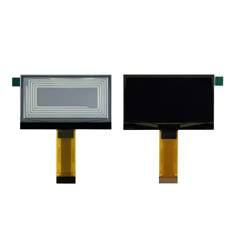
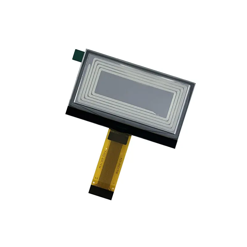
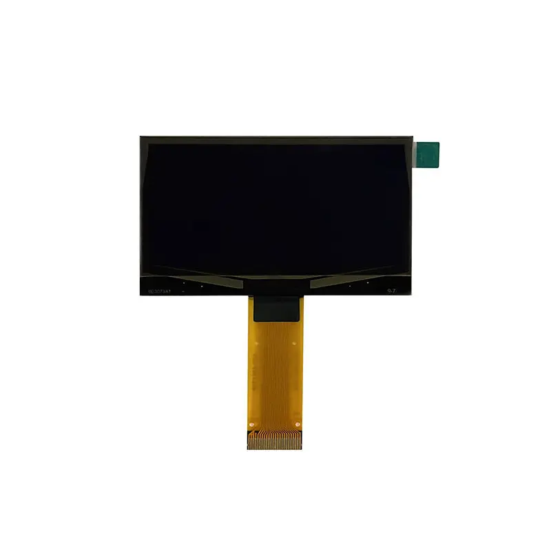
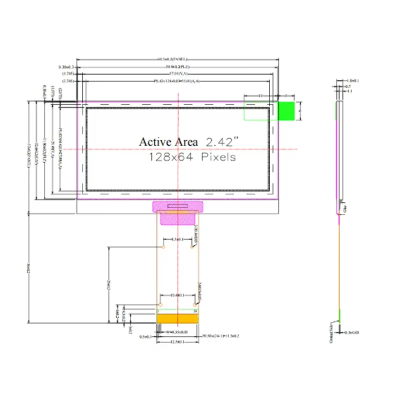
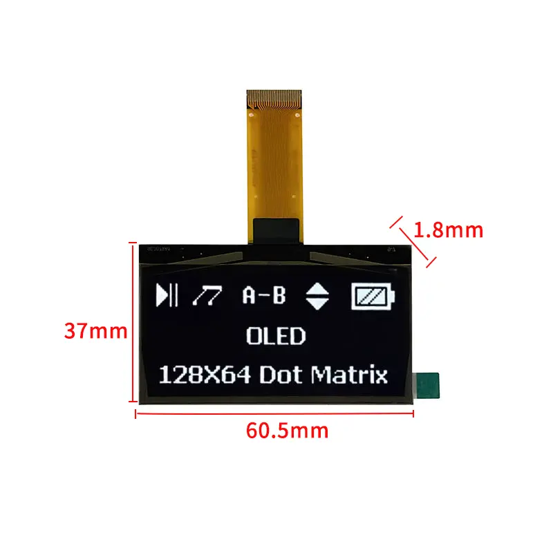
This Monochrome PMOLED Graphic Display provides a white 128 × 64 dot matrix for operating values, symbols, menus, alerts, and compact status graphics. Its COG structure combines a 55.01 × 27.49 mm active area with a 60.5 × 37.0 × 1.8 mm module outline, making it suitable for embedded interfaces where panel depth and front-surface area are limited.
The panel supports selectable parallel, 4-wire SPI, or I2C architectures through the production configuration. Interface mode, pin assignment, voltage requirements, and initialization support must be verified before the host PCB is released.
Product Summary
The display uses passive-matrix OLED technology with white monochrome emission and a 1/64 duty configuration. Because OLED pixels emit their own light, the module does not require an LCD backlight.
A 128 × 64 matrix is suitable for functional information rather than photo-oriented content. It can present numeric values, short text labels, icons, progress indicators, battery symbols, menu cursors, and simple line graphics within a compact display window.
The 128 × 64 matrix is suitable for monochrome values, menus, symbols, and status graphics rather than photo-oriented content.
Key Specifications
| Specification | Value |
|---|---|
| Display technology | COG PMOLED |
| Matrix type | Passive matrix |
| Display size | 2.42 inches |
| Resolution | 128 × 64 dots |
| Display color | Monochrome white |
| Drive duty | 1/64 duty |
| Active area | 55.01 × 27.49 mm |
| Module dimensions | 60.5 × 37.0 × 1.8 mm |
| Pixel pitch | 0.43 × 0.43 mm |
| Pixel size | 0.40 × 0.40 mm |
| Weight | 2.18 g |
| Controller IC | SSD1309 |
| Interface options | 6800/8080 parallel, 4-wire SPI, or I2C |
| Touch | Non-touch |
| Backlight | None |
Designing a 128 × 64 Monochrome Interface
Text, Symbols, and Status Graphics
The matrix can support compact interface elements such as:
- instrument readings
- operating modes
- warning symbols
- battery indicators
- connection status
- short menu labels
- progress bars
- channel numbers
- timer values
- simple trend or level graphics
The interface should be designed for the actual pixel grid. Long sentences and small proportional fonts can become difficult to read, while concise labels and purpose-built bitmap icons use the available area more effectively.
Bitmap and Font Planning
Engineering should define:
- character height and width
- minimum stroke thickness
- spacing between text rows
- icon dimensions
- bitmap storage format
- screen-buffer organization
- update regions
- inversion behavior
- scrolling requirements
- language-character requirements
A full-screen monochrome bitmap requires 1,024 bytes when stored as one bit per pixel, before firmware overhead or alternative memory organization. The actual buffer structure depends on the host library and controller addressing method.
Interface Selection for the Monochrome PMOLED Graphic Display
The Monochrome PMOLED Graphic Display can be configured for an 8-bit 6800/8080-style parallel bus, 4-wire SPI, or I2C. These options should be treated as production configurations rather than assumed simultaneous interfaces.
Parallel, SPI, and I2C Tradeoffs
A parallel interface uses more host pins but can transfer display data through a wider bus. It may suit controller boards with available GPIO and established 6800- or 8080-style display support.
Four-wire SPI reduces signal count and provides separate clock, data, chip-select, and data/command control. It is often suitable when the host has a dedicated SPI peripheral and moderate update rates are required.
I2C uses fewer signal lines, but available bandwidth, device addressing, and controller configuration must be checked against the required screen-update behavior.
Production Configuration Verification
Before selecting the host architecture, confirm:
- enabled interface mode
- complete FPC pin assignment
- control-signal polarity
- logic voltage
- OLED panel voltage
- reset requirements
- data/command handling
- chip-select behavior
- serial clock limits
- I2C address
- interface-selection pins
- initialization sequence
- command-set support
- FPC pitch and contact direction
The selected parallel, SPI, or I2C interface configuration must be confirmed on the production FPC and datasheet.
A product family may support several bus types while an individual FPC is wired for only one approved configuration.
SSD1309 Integration Boundaries
SSD1309 is the identified controller IC. Comparable SSD1309 modules commonly support 128 × 64 monochrome graphics and parallel, SPI, or I2C options, but the exact electrical and software implementation still depends on the production module.
The controller name does not independently establish:
- the active bus mode
- logic voltage
- OLED supply voltage
- pin sequence
- initialization commands
- segment or common remapping
- display orientation
- contrast settings
- charge-pump arrangement
- current consumption
- host-library compatibility
SSD1309 identifies the controller family but does not prove a host-compatible pinout, voltage plan, or initialization sequence.
The approved datasheet, pin definition, reference circuit, and initialization package should be reviewed together.
Mechanical and FPC Integration
The module measures 60.5 × 37.0 × 1.8 mm, with a 55.01 × 27.49 mm active area. The pixel pitch is 0.43 × 0.43 mm, and each emitting pixel measures 0.40 × 0.40 mm.
The 2.18 g display weight is useful for compact handheld or panel-mounted electronics, but the complete assembly weight will also include the PCB, connector, cover, support frame, adhesive, and enclosure.
Mechanical review should include:
- visible opening
- inactive border
- FPC exit position
- FPC bend radius
- connector location
- module support
- adhesive area
- cover clearance
- front-panel tolerance
- assembly pressure
- polarizer protection
- handling procedure
The 1.8 mm module thickness does not include a custom cover, support frame, breakout PCB, or additional protective structure.
OLED Power and Image Qualification
OLED pixels are self-emissive, so current demand can vary with the number of illuminated pixels, display content, contrast setting, update pattern, and selected electrical configuration.
The production design should qualify:
- logic and OLED supply rails
- startup and shutdown sequence
- peak and average current
- active-pixel percentage
- contrast setting
- sleep behavior
- full-screen versus partial-screen updates
- image-retention risk
- long-duration static content
- thermal conditions
- expected operating lifetime
Static icons or labels that remain continuously illuminated should be included in the sample test plan. Screen blanking, content movement, or controlled contrast settings may be considered where long static operation is expected, subject to the approved design documentation.
Recommended Applications
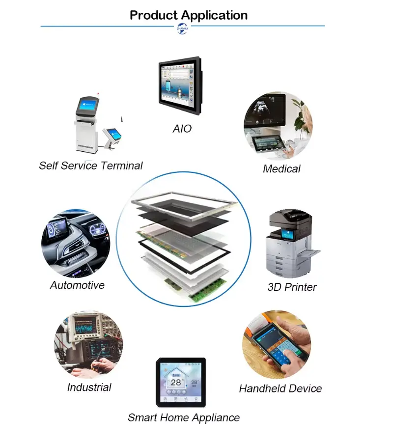
The module can be evaluated for:
- measurement instruments
- compact control panels
- handheld electronic devices
- household-device status panels
- communication equipment
- portable service tools
- embedded menu displays
- sensor interfaces
- battery-powered status products
- small industrial controls
Medical, automotive, outdoor, hazardous-location, or safety-critical use requires separate system qualification and applicable compliance evidence.
Customization and Sample Approval
Project review may cover:
- FPC shape and length
- pin definition
- selected interface mode
- display orientation
- emission color
- module outline
- active-area position
- connector arrangement
- graphic presentation
- packaging
- branding
Custom configurations are generally reviewed from 500 pieces, subject to tooling requirements, material availability, and the requested specification. Sample and standard-module quantities are confirmed separately.
Sample testing should use the intended host MCU, production pinout, voltage rails, initialization commands, interface frequency, display content, enclosure, and operating pattern.
Procurement Checklist
Submit:
- host MCU or processor
- selected interface mode
- 6800 or 8080 parallel requirement, where applicable
- SPI clock and control requirements
- I2C addressing requirements
- logic voltage
- OLED supply design
- complete FPC pin map
- connector pitch and contact direction
- initialization command package
- required screen orientation
- bitmap and font examples
- expected update rate
- maximum illuminated-pixel percentage
- power budget
- static-content duration
- enclosure opening
- FPC routing
- environmental targets
- sample quantity
- annual demand
- required compliance documents
FAQ
About 2.42 Inch Monochrome PMOLED Graphic Display for Instruments
What must be checked before connecting the display to an MCU?
How should parallel, SPI, and I2C be compared for this module?
Can a generic SSD1309 library drive this display directly?
What information should be prepared for the 128 × 64 UI?
How does this bare panel differ from an OLED breakout board?
What should be validated for long-duration static content?
Freya Yang
+86 18318948097
