Freya Yang
+86 18318948097
+852 62667476
2.73 Inch Industrial Instrument Display Module for Control Panels
Model P/N
Size
Resolution
Brightness
Viewing Angle
Connector Type
Operating Temp
Overall(mm)
huisoar
HS0273QHO1A-V1
Brand
Panel Size (inch)
Model P/N
Resolution
Brightness (nits)
Viewing Angle
Contrast Ratio
Response Time
Overall (mm)
Active Area (mm)
Refresh Rate
Display Colors
Panel Type
Connector Type
Operating Temp
Touchscreen Type
Storage Temp
Work Mode
Control Type
Operating Environment
Designed For
2.73 Inch Industrial Instrument Display Module for Control Panels
A square 320 × 320 TFT with 450 cd/m² luminance gives compact control-panel designs a balanced canvas and flexible SPI3W + RGB18 integration.
Product Summary
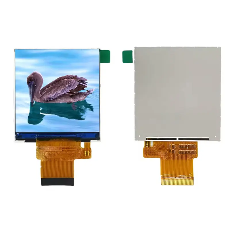
The Industrial Instrument Display Module provides a compact 2.73-inch square screen for equipment that needs balanced status graphics, menus, icons, alarms, and measurement data. Its native 320 × 320 raster maps naturally to square interface layouts without forcing a wide-screen design into a small enclosure.
It combines 450 cd/m² luminance, all-view positioning, 16.7M colors, and an SPI3W + RGB18BIT interface label. The approved pinout must define the exact role of each signal because a combined SPI and RGB designation does not prove that SPI alone carries full-frame pixel data.
No touch panel, connector pin count, supply voltage, contrast ratio, response time, storage-temperature range, or backlight lifetime is confirmed for the standard configuration.
Key Specifications
| Parameter | Confirmed value |
|---|---|
| Display size | 2.73 inches |
| Native resolution | 320 × 320 pixels |
| Screen format | Square, 1:1 pixel raster |
| Display technology | TFT LCD |
| Luminance | 450 cd/m² |
| Viewing description | All View |
| Display colors | 16.7M colors |
| Interface label | SPI3W + RGB18BIT |
| Driver IC | ST7796 / ST7365; exact variant requires confirmation |
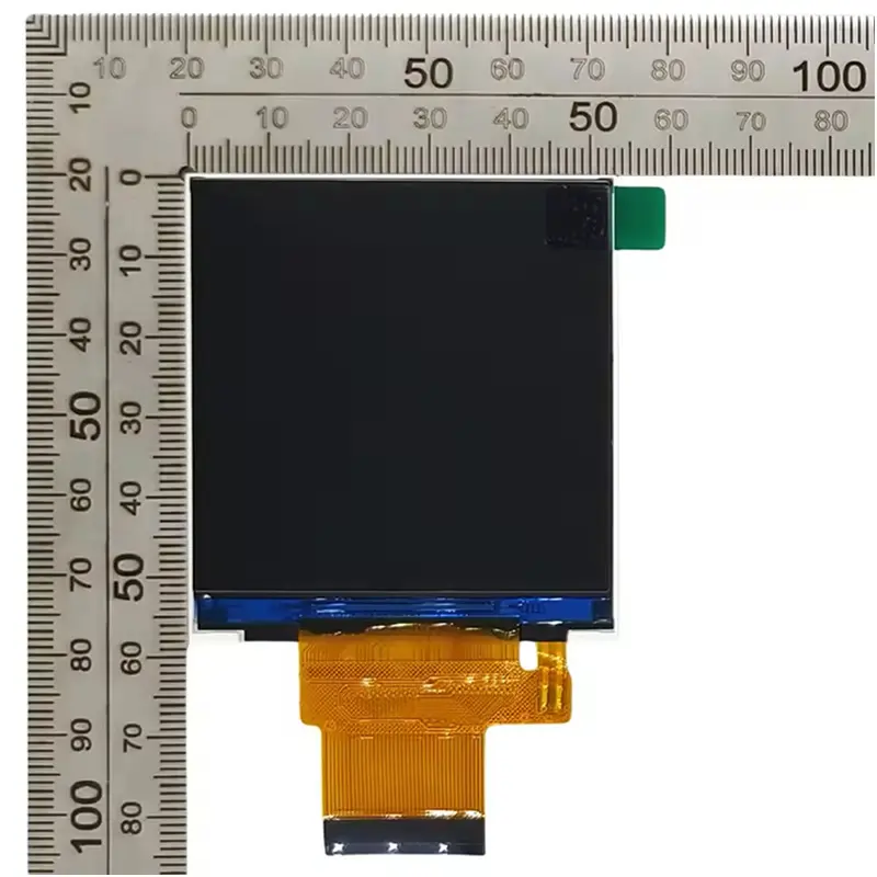
| Active area | 48.96 × 48.96 mm |
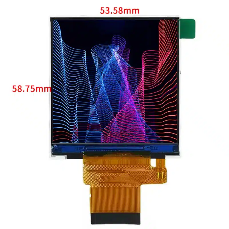
| LCM outline | 53.58 × 58.75 mm; thickness not confirmed |
| Backlight | Six white LEDs in parallel |
| Operating temperature | −20°C to +70°C |
| Touch | Not confirmed |
Square 320 × 320 Interface Design
Native Square UI Planning
The 320 × 320 raster supports centered gauges, status rings, tiled menus, compact trend plots, icon grids, and symmetric control layouts. Use native-resolution assets to preserve text clarity and alignment. UI teams should also reserve space for the physical border and verify the visible opening against the 48.96 × 48.96 mm active area.
The square format suits enclosures with similar width and height constraints, but it does not establish a circular viewing window or guarantee use of every pixel without masking.
450 cd/m² and All-View Positioning
The 450 cd/m² configuration is appropriate for indoor industrial equipment and other controlled or moderately bright installations after front-cover losses are considered. It does not establish direct-sun readability. Final approval should use the intended cover lens, bonding method, installation angle, and ambient light.
“All View” indicates broad viewing performance but does not provide a verified left/right/up/down angle sequence. Do not publish numerical viewing angles until the approved datasheet defines them.
Color and Backlight Boundaries
The 16.7M-color capability supports color-coded alarms, process states, icons, and graphical menus. The six-white-LED backlight statement identifies the emitter count and parallel arrangement, but it does not define forward voltage, total current, enable behavior, dimming method, thermal limits, or driver requirements.
Integrating the Industrial Instrument Display Module
SPI3W + RGB18 Signal Qualification
The interface label indicates a combined three-wire SPI and 18-bit RGB architecture. Engineering must verify the SPI function and whether RGB18 carries continuous pixel data. Before PCB release, confirm the complete FPC assignment, pixel clock, sync or DE behavior, RGB mapping, logic voltage, reset, and scan direction.
A processor that supports only serial SPI should not be assumed to drive this module at the required image-update rate. Conversely, an RGB-capable host still needs the correct SPI control path when the ordered configuration requires it.
Driver-IC Variant Control
The configuration family names ST7796 and ST7365, but the exact driver assignment for the V1 configuration is not established. A driver-IC family name does not guarantee a drop-in command set, initialization sequence, pin map, voltage plan, or software library.
Confirm the model-specific command documentation and sample marking before software is frozen.
FPC, Pinout, and Power Documentation
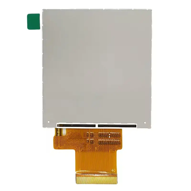
The bottom FPC is visible, but its pin count, pitch, contact side, bend zone, and connector recommendation are not confirmed. These details control cable selection, PCB placement, strain relief, and clearance.
Panel logic and LED-backlight power must also be documented separately. The backlight driver should not be released from the LED count alone.
Mechanical Fit for Compact Control Panels
Active Area and Outline Dimensions
The active image area measures 48.96 × 48.96 mm. The LCM outline is 53.58 × 58.75 mm, so the module extends beyond the square active area to accommodate the panel structure and FPC region. Thickness is not confirmed and must be taken from the approved drawing before enclosure tooling.
Use the mechanical drawing to check bezel overlap, visible opening, datum positions, FPC exit, bend radius, keep-out zones, adhesive areas, and support points.
Temperature Range and Enclosure Planning
The confirmed operating range is −20°C to +70°C. Finished equipment should still be tested for cold start, high-temperature image stability, backlight heating, condensation, and FPC stress. Storage temperature and humidity limits require separate confirmation.
Application Fit for Industrial Equipment
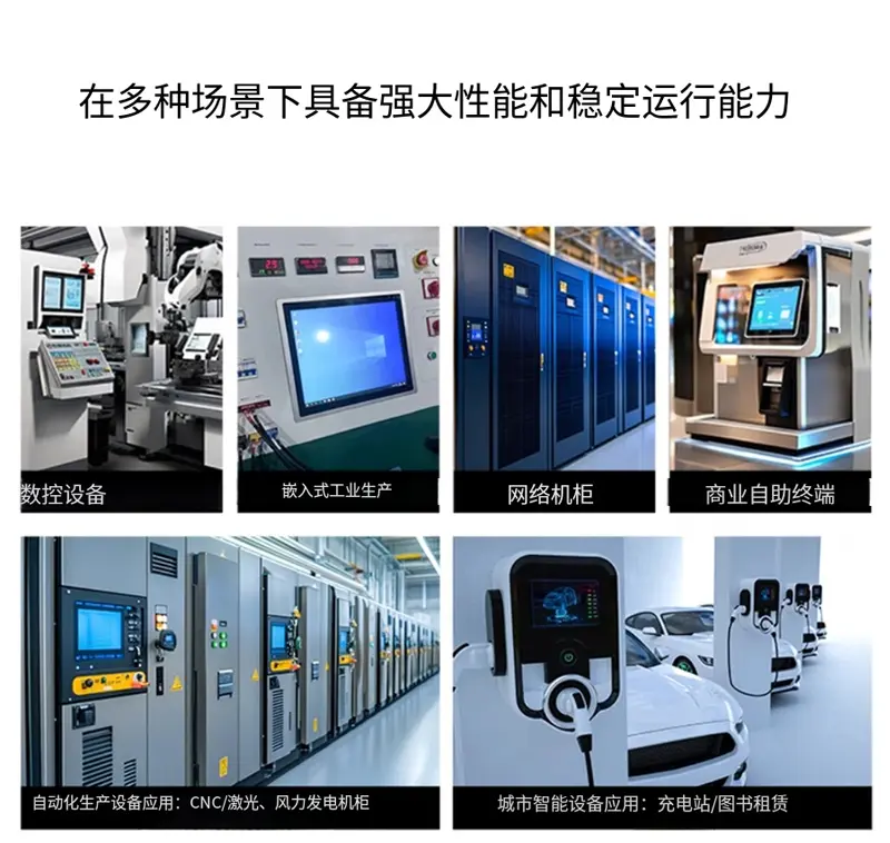
This Industrial Instrument Display Module is suited to compact process-control panels, measurement instruments, sensor interfaces, smart controllers, equipment status displays, and selected smart-home or security subpanels after host and mechanical qualification.
The 450 cd/m² rating, all-view wording, and operating-temperature range support broad equipment design, but they do not establish waterproofing, vibration grade, impact resistance, EMC compliance, automotive qualification, medical certification, or outdoor-system approval.
Customization and Procurement
Resolution and brightness customization is generally reviewed from 1,000 sets. Drawing-based, sample-based, and full-custom projects may also cover FPC design, interface definition, cover structure, optical treatment, branding, and packaging, subject to feasibility.
Standard purchasing may begin from one set, but sample, production, timing, and customization terms should be reconfirmed for the selected variant.
Procurement Checklist
Confirm:
- Assigned and supplier model references
- Native 320 × 320 orientation and scan direction
- Exact V1 driver IC and command documentation
- SPI3W function and RGB18 timing
- Complete FPC pinout, pitch, contact side, and orientation
- Logic voltage and I/O levels
- Pixel clock, sync or DE requirements, and RGB bit mapping
- Backlight voltage, current, enable, dimming, and thermal limits
- Six-LED parallel topology and driver design
- 48.96 × 48.96 mm active-area position
- 53.58 × 58.75 mm outline and missing thickness
- Cover-lens, bonding, and ambient-light target
- Touch requirement
- Operating and storage limits
- Sample criteria, annual demand, and customization scope
FAQ
About 2.73 Inch Industrial Instrument Display Module
Can the module be driven through three-wire SPI alone?
What must be checked before replacing another 2.73-inch 320 × 320 display?
Which driver IC applies to the V1 configuration?
Is 450 cd/m² sufficient behind a cover lens?
What backlight information is required before designing the driver?
Freya Yang
+86 18318948097