Freya Yang
+86 18318948097
+852 62667476
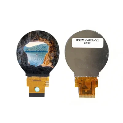
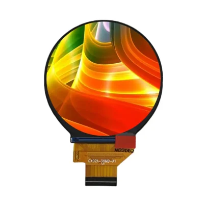
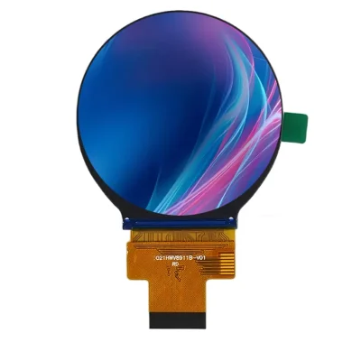
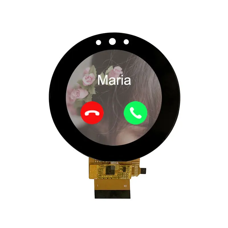
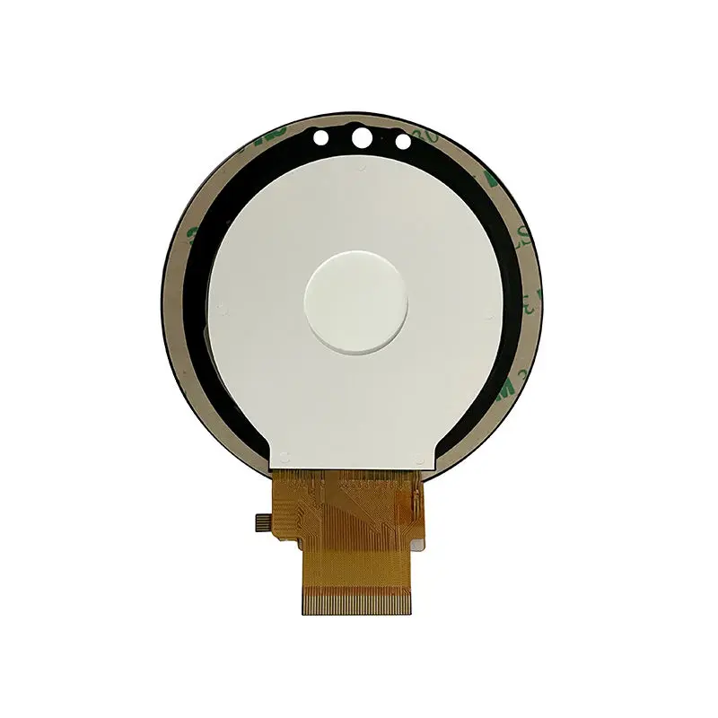
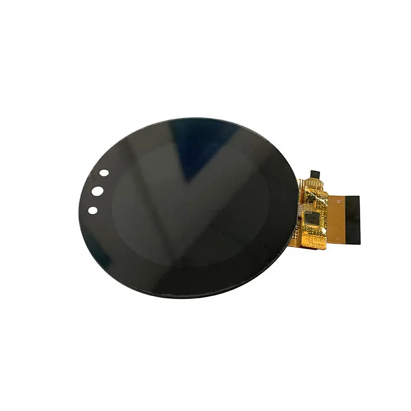
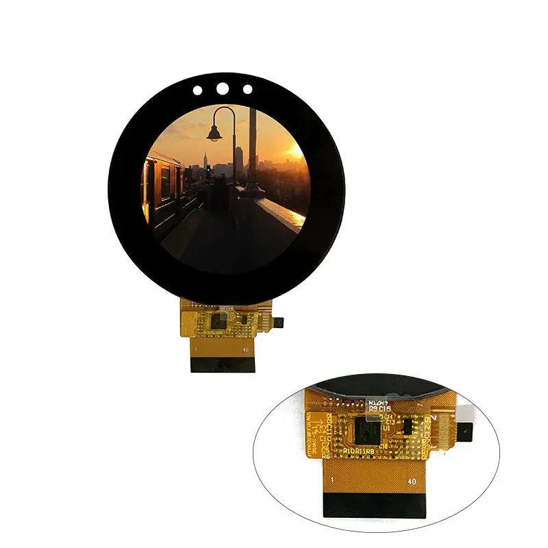
2.1 Inch Round RGB SPI Touch Display Module for Smart Handhelds
Model P/N
Size
Resolution
Brightness
Viewing Angle
Connector Type
Operating Temp
Overall(mm)
huisoar
HS021GFFO1ASVO2AV1
Brand
Panel Size (inch)
Model P/N
Resolution
Brightness (nits)
Viewing Angle
Contrast Ratio
Response Time
Overall (mm)
Active Area (mm)
Refresh Rate
Display Colors
Panel Type
Connector Type
Surface Treatment
Operating Temp
Touchscreen Type
Storage Temp
Work Mode
Pixel Format
Input Voltage (V)
Control Type
Operating Environment
Designed For
2.1 Inch Round RGB SPI Touch Display Module for Smart Handhelds
Built for circular handheld interfaces, this 480 × 480 normally black TFT combines an 18-bit RGB image path, 3-wire SPI control and an I2C capacitive touch layer.
Product Summary
The Round RGB SPI Touch Display Module is a 2.1-inch integrated TFT and capacitive-touch assembly for smart handheld controls, compact HMIs, smart-home interfaces and qualified VR/AR devices. Its 480 × 480 raster supports circular menus, status rings and gauges within a 53.28 × 53.28 mm active area.
The a-Si IPS TFT uses normally black transmissive mode, RGB vertical stripes and 16.7 million colors. The LCD combines an 18-bit parallel RGB bus with 3-wire SPI control, while the projected-capacitive touch panel communicates through a separate I2C path.
Key Specifications
| Parameter | Confirmed value |
|---|---|
| Display size | 2.1 inches |
| Resolution | 480 × 480 pixels |
| Panel type | a-Si IPS TFT with integrated CTP |
| Display mode | Normally black, transmissive |
| Display colors | 16.7 million |
| Active area | 53.28 × 53.28 mm |
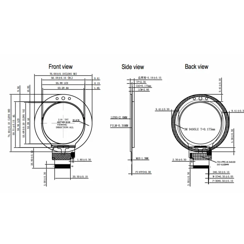
| Assembly outline | 75.00 ± 0.10 × 74.49 ± 0.10 × 5.19 ± 0.15 mm |
| Pixel pitch | 0.111 × 0.111 mm |
| Pixel density | 324 PPI |
| LCD interface | 18-bit RGB parallel plus 3-wire SPI |
| Touch interface | I2C |
| LCD driver reference | ST7701S |
| Touch controller reference | ATMXT308U |
| Luminance | 320 cd/m² typical |
| Contrast ratio | 1000:1 maximum at peak viewing angle |
| Viewing direction | All-direction wording |
| Response time | 30 ms typical |
| Cover-lens hardness | 6H specification |
| Backlight | LED |
| Backlight life | 10,000 hours minimum under the listed test condition |
| LCD module supply | 2.8 V |
| Operating temperature | −20°C to +70°C |
| Storage temperature | −30°C to +80°C |
480 × 480 Circular UI and Optical Planning
Use the Native Raster and a Circular Safe Area
The panel is addressed as a square 480 × 480 pixel matrix even though the visible interface is circular. Prepare native-resolution artwork and keep critical labels and touch targets away from the curved edge. Overlay the cover printing, bezel and assembly tolerance before freezing fonts, icons and radial controls.
Validate 320 cd/m² Behind the Cover Lens
The controlled luminance value is 320 cd/m² typical. It supports indoor and controlled-light evaluation, but does not establish direct-sunlight readability. The final result depends on lens transmittance, reflections, printed border, bonding and installation angle. Test a representative assembly under the intended lighting rather than replacing the confirmed value with the marketing phrase “high brightness.”
Round RGB SPI Touch Display Module Integration
Separate Pixel Transport from Panel Control
The 18-bit RGB bus carries continuous pixel data, while 3-wire SPI handles panel-control communication. The host must provide the required RGB timing and SPI path. The interface name alone does not establish pixel clock, sync mode, porch values, signal voltage, scan direction or initialization compatibility.
Request the approved timing table, complete 40-pin LCD FPC definition and revision-specific command package. ST7701S identifies the LCD driver reference but does not replace those documents.
Keep the I2C Touch Path Independent
The capacitive-touch controller uses I2C rather than the LCD’s RGB or SPI data path. The touch drawing shows a separate seven-position connection with power, reset, clock, data, interrupt and ground functions. Reconcile the exact pin names and electrical limits against the approved revision.
Qualify the Touch Controller
ATMXT308U identifies the touch-controller reference. It does not confirm the I2C address, report format, configuration set, reset timing or firmware revision. Test coordinate mapping, edge response, noise immunity and reset recovery in the finished enclosure.
CTP Mechanics and Enclosure Fit
Use the Full Touch-Assembly Envelope
The complete assembly measures 75.00 ± 0.10 × 74.49 ± 0.10 × 5.19 ± 0.15 mm with CTP. The active image area is 53.28 × 53.28 mm, so enclosure release must use the full lens and assembly drawing.
The drawing identifies a 2.0 mm cover lens and G+F+F touch structure. Verify printed-border alignment, adhesive clearance, mounting pressure and the bottom-tail exit.
Qualify Both FPC Paths
Confirm the 40-pin LCD FPC and seven-position touch FPC for pitch, contact side, mating connector, insertion direction, bend radius and strain relief. Include cable overlap and fold zones in the first mechanical prototype.
Power, Temperature and Lifetime References
Separate LCD, Touch and Backlight Requirements
The LCD module supply is listed as 2.8 V. The touch drawing also identifies 3.3 V supply and I/O references, which require ordered-revision confirmation. Neither value defines the LED-backlight driver requirement.
Request current consumption, rail tolerances, startup order, reset timing, backlight voltage/current and dimming method before completing the power design.
Apply the Lifetime Grade With Its Test Condition
The LED backlight is rated at 10,000 hours minimum under the listed 25°C and 15 mA RMS condition. This conditional reference is not a finished-product life guarantee. The component operates from −20°C to +70°C and stores from −30°C to +80°C; system qualification should also cover the touch layer, adhesives, lens and FPCs.
Applications and Qualification Boundaries
The Round RGB SPI Touch Display Module can be evaluated for smart handheld controls, compact operator interfaces, smart-home dials, portable instruments and VR/AR control surfaces. Its circular UI and integrated touch suit products requiring direct interaction in a compact front-panel geometry.
Application wording does not establish medical, automotive, outdoor, waterproof, impact or vibration certification. Regulated or harsh-environment projects require separate qualification.
Configuration and Customization
Branding, packaging and graphic customization are listed from 100 sets. FPC geometry, connector definition, cover-lens graphics, touch tuning, luminance, bonding, backlight and mechanical changes require engineering review. Samples and standard-module quantities are confirmed independently.
Procurement Checklist
Confirm before sample approval:
- Assigned and supplier model numbers and drawing revision
- Native 480 × 480 timing and circular UI safe area
- RGB18 mapping, pixel clock and sync/DE mode
- 3-wire SPI command path and initialization package
- Complete 40-pin LCD and seven-position CTP definitions
- ST7701S and ATMXT308U documentation
- LCD, touch and backlight voltage/current requirements
- 53.28 × 53.28 mm active-area alignment
- 75.00 × 74.49 × 5.19 mm enclosure fit
- Cover-lens print, bonding and touch-coordinate mapping
- 320 cd/m² lighting target
- Temperature, sample criteria, quantity and annual demand
FAQ
What must be checked before connecting the RGB18-bit and 3-wire SPI interface?
How are the LCD and capacitive-touch interfaces separated?
Which dimensions should control the enclosure design?
Is 320 cd/m² sufficient behind the final cover lens?
What information is required to approve the two controller references?
Freya Yang
+86 18318948097