Freya Yang
+86 18318948097
+852 62667476
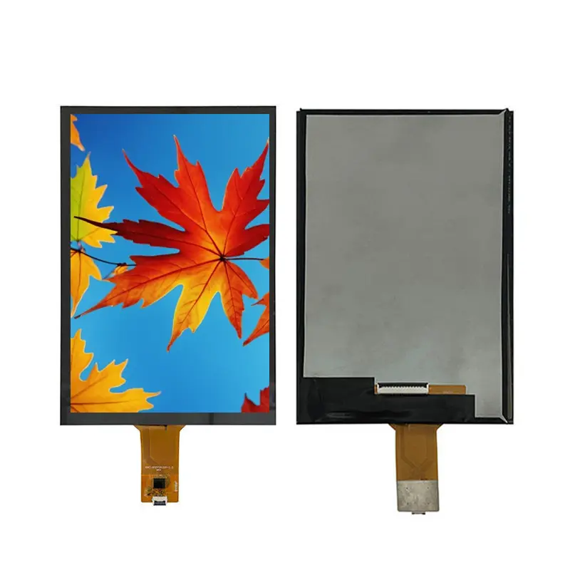
7 Inch Portrait Capacitive Display Module for Smart Terminals
Model P/N
Size
Resolution
Brightness
Viewing Angle
Connector Type
Operating Temp
Overall(mm)
huisoar
HS070WX49A-V1
Brand
Panel Size (inch)
Model P/N
Resolution
Brightness (nits)
Viewing Angle
Contrast Ratio
Response Time
Overall (mm)
Active Area (mm)
Refresh Rate
Display Colors
Panel Type
Connector Type
Operating Temp
Touchscreen Type
Storage Temp
Work Mode
Pixel Format
Control Type
Operating Environment
Designed For
7 Inch Portrait Capacitive Display Module for Smart Terminals
A slim 800×1280 MIPI touch display for portrait smart-terminal and embedded-control interfaces.
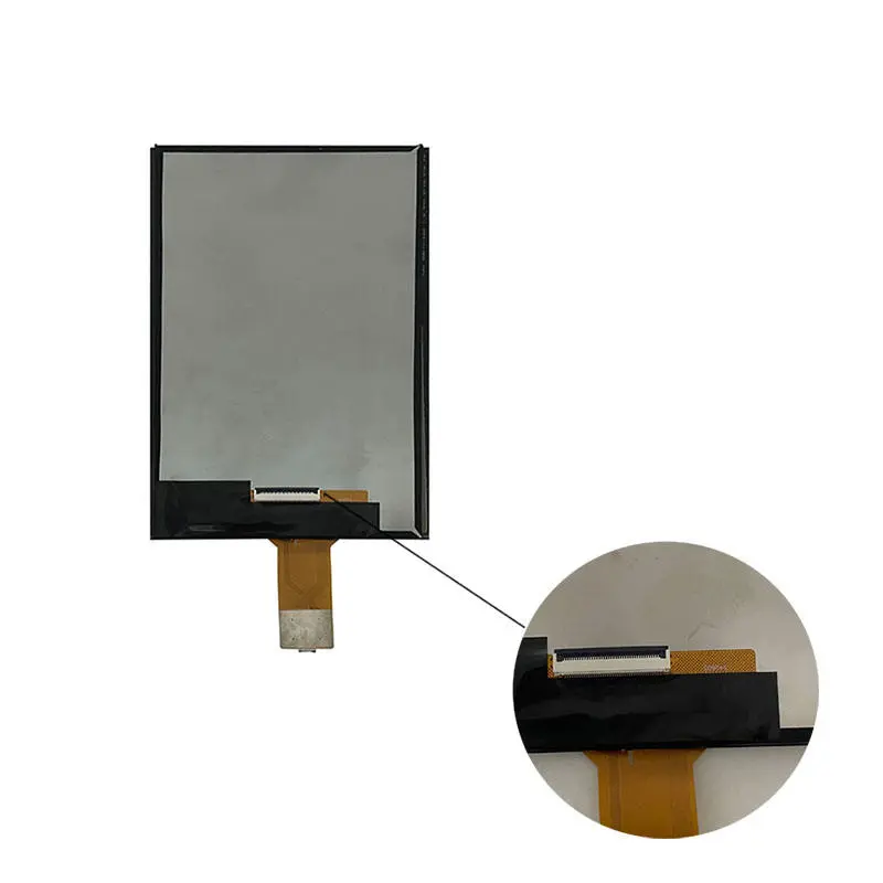
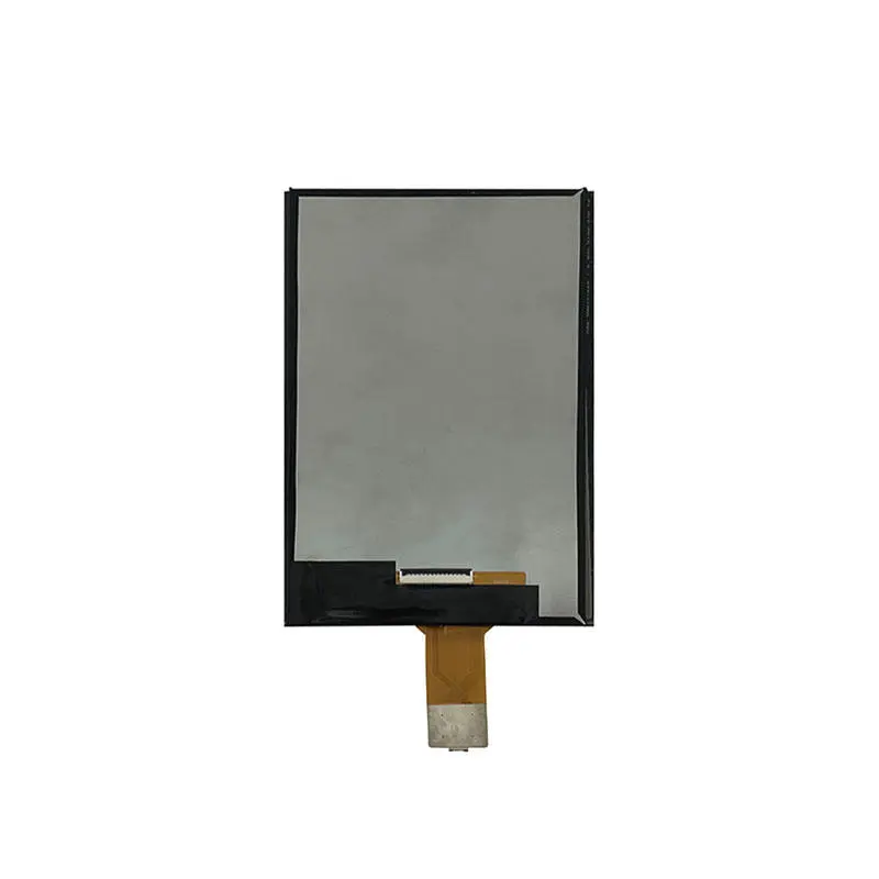
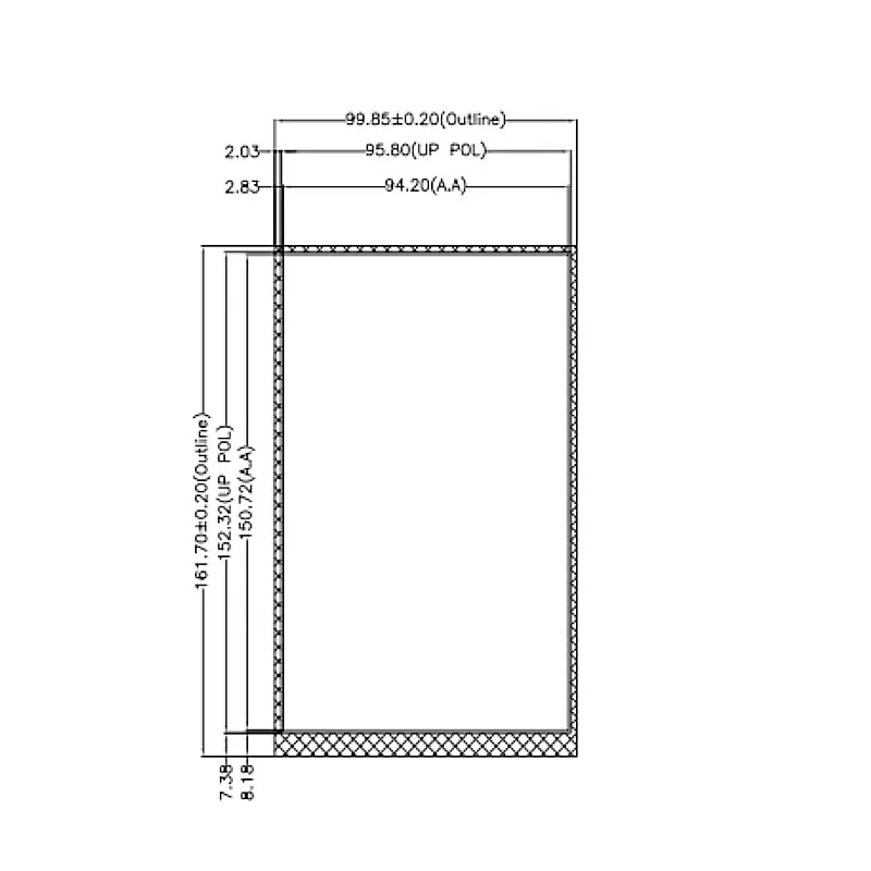
The 7 Inch Portrait Capacitive Display Module is an 800×1280 normally-black TFT component for smart terminals, compact controllers and portrait embedded HMIs. It combines MIPI 4-lane display input, a capacitive-touch configuration, 350 cd/m² typical luminance, 800:1 typical contrast and a slim 161.00 × 99.75 × 2.40 mm module structure.
The active image area measures 150.72 × 94.20 mm. Final compatibility depends on the approved MIPI timing, lane assignment, connector pinout, voltage requirements, touch-controller interface and FPC orientation.
Key Specifications at a Glance
| Parameter | Confirmed value |
|---|---|
| Display size | 7.0 inch |
| Resolution | 800 × 1280 pixels |
| Display technology | TFT LCD |
| Display mode | Normally black |
| Viewing statement | All-o’clock viewing |
| Brightness | 350 cd/m² typical |
| Contrast ratio | 800:1 typical |
| Display colors | 16.7 million colors |
| Interface | MIPI 4-lane |
| Driver IC | JD9365 |
| Touch | Capacitive touch configuration |
| Active area | 150.72 × 94.20 mm |
| Module outline | 161.00 × 99.75 × 2.40 mm |
| Pixel pitch | 0.11775 × 0.11775 mm |
| Backlight | 20 white LEDs |
| Operating temperature | −10°C to +50°C |
| Storage temperature | −20°C to +60°C |
Final production design should follow the approved electrical specification, touch specification, mechanical drawing and qualified sample.
800×1280 Portrait Interface Design
The native 800×1280 format supports vertically organized interfaces with sufficient room for graphics, data, status information and touch-operated controls.
Portrait UI planning
A smart-terminal layout can allocate space for:
- Main operating or information area
- Status and connectivity indicators
- Touch navigation controls
- Notifications and alarm messages
- Device settings
- Measurement or transaction information
- Footer actions
Application graphics should be rendered at the native resolution whenever practical. Unnecessary scaling can soften text, distort icons or leave unusable screen areas.
Normally-black visual behavior
The panel is identified as normally black, which suits dark-themed control interfaces and applications that use illuminated graphics against a dark background.
Normally-black operation does not independently prove a particular black level, color gamut or optical performance under every viewing condition. These characteristics should be reviewed on the qualified sample.
350 cd/m² Viewing Environment
The standard luminance is 350 cd/m² typical. This level is primarily suited to indoor devices and controlled-light equipment.
Optical-stack effects
Final readability also depends on:
- Touch-sensor reflectance
- Cover-lens construction
- Air gap or bonding method
- Surface treatment
- Enclosure angle
- Ambient lighting
- Backlight control
- UI color contrast
The standard 350 cd/m² version should not be described as sunlight-readable.
Contrast and viewing statement
The display has an 800:1 typical contrast ratio and an all-o’clock viewing statement. Numerical viewing-angle values are not specified, so the final viewing result should be evaluated with the intended touch stack, enclosure and cover.
MIPI 4-Lane Host Compatibility
The 7 Inch Portrait Capacitive Display Module uses a MIPI 4-lane display route. The host processor must supply the correct timing, lane order, voltage levels, control signals and native image data.
A MIPI 4-lane label does not guarantee compatibility with another MIPI display.
Required display checks
Confirm before PCB release:
- MIPI lane count
- Clock-lane assignment
- Data-lane order and polarity
- Native 800×1280 timing
- Complete display pin assignment
- Logic and panel voltages
- Reset and synchronization signals
- FPC pitch and contact side
- Connector orientation
- Backlight connections
Connector shape or pin count alone is not sufficient to establish electrical compatibility.
Non-MIPI hosts require conversion
HDMI, USB, LVDS, eDP and parallel RGB cannot connect directly without suitable interface-conversion hardware.
Controller-board selection must use the complete timing, lane, voltage and pin requirements rather than screen size and resolution alone.
JD9365 technical boundary
JD9365 is identified as the TFT driver IC.
The driver identifier does not by itself establish universal processor compatibility, a host-side register-programming requirement or a particular power sequence. The complete module timing, control and electrical requirements must govern system integration.
Capacitive-Touch Integration
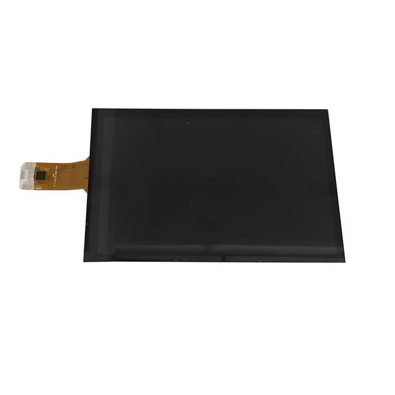
Capacitive touch is identified for the product configuration, but the available product facts do not confirm the touch-controller model, communication protocol or touch-point count.
Display and touch are separate subsystems
The MIPI connection carries LCD image data. The touch function requires a separately confirmed control path.
Before design approval, confirm:
- Touch-controller part number
- Touch communication protocol
- Touch operating voltage
- Interrupt and reset signals
- Touch FPC pin assignment
- Required touch-point count
- Cover-lens dimensions
- Bonding structure
- Firmware support
Capacitive touch does not automatically confirm multi-touch, glove operation, water rejection or operating-system compatibility.
Mechanical and Backlight Integration
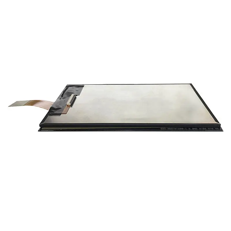
The LCD module measures 161.00 × 99.75 × 2.40 mm. Its slim profile supports compact equipment, but the finished product will be thicker after adding the touch stack, cover, adhesive, PCB, mounting parts and enclosure.
Active area and enclosure window
The active area is 150.72 × 94.20 mm. The front opening must account for:
- LCD outside dimensions
- Visible image area
- Bezel overlap
- Touch-sensor outline
- Cover-lens outline
- Mechanical tolerances
- FPC exit position
- Connector clearance
The enclosure opening should be finalized from the complete controlled drawing rather than the active-area dimensions alone.
Backlight qualification
The module uses 20 white LEDs. A compatible backlight-driver design must follow the approved electrical specification.
The LED count does not establish backlight lifetime, dimming method, total power consumption or higher-brightness capability.
Recommended Applications
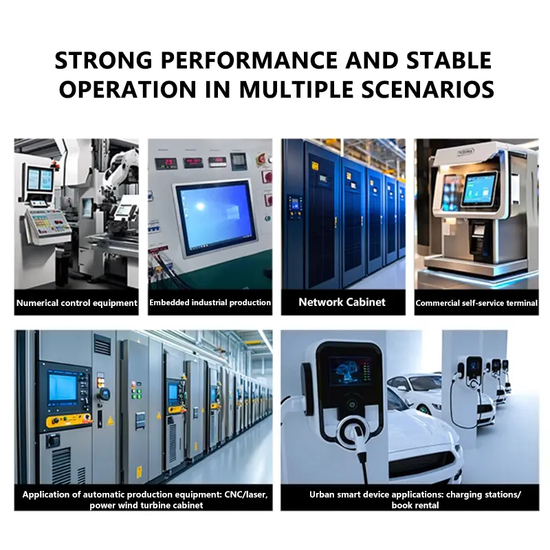
The 7 Inch Portrait Capacitive Display Module may be evaluated for:
- Smart control terminals
- Smart-home panels
- Handheld controllers
- Portrait embedded HMIs
- Portable test and service equipment
- Compact information terminals
- POS operator interfaces
- Data-collection equipment
A different solution may be more suitable when the system requires direct HDMI input, higher standard luminance, verified outdoor readability, a landscape-native format, a specified touch controller or an included controller board.
Customization and Project Qualification
Project review may cover:
- MIPI lane and timing requirements
- Display connector and pin definition
- FPC shape and routing
- Capacitive-touch configuration
- Touch-controller selection
- Cover-lens construction
- Brightness target
- Mechanical adaptation
- Controller-board matching
- Packaging and branding
Custom configurations are generally reviewed from 1,000 pieces, subject to tooling requirements, material availability and the requested specification. Sample and standard-module quantities are confirmed separately.
Procurement Checklist
Before sample approval, confirm:
- Native 800×1280 portrait UI
- MIPI 4-lane host support
- Clock and data-lane mapping
- Complete display pin assignment
- Logic and panel voltages
- FPC pitch, contact side and orientation
- JD9365 datasheet-defined module requirements
- Touch-controller identity
- Touch communication interface
- Touch FPC pin assignment
- Required touch-point count
- Active area: 150.72 × 94.20 mm
- Module outline: 161.00 × 99.75 × 2.40 mm
- Complete touch and cover drawing
- 350 cd/m² lighting suitability
- Backlight-driver requirements
- Operating temperature: −10°C to +50°C
- Storage temperature: −20°C to +60°C
- Sample quantity and annual demand
- Controller requirement and production timing
FAQ
About 7 Inch Portrait Capacitive Display Module
How should an 800×1280 portrait interface be planned for a 7-inch screen?
Is the 150.72 × 94.20 mm active area the correct enclosure opening size?
How can the portrait orientation affect MIPI routing and PCB placement?
What symptoms may indicate incorrect MIPI lane order or timing?
How should the −10°C to +50°C operating range be applied in enclosure design?
What must be verified before selecting a capacitive-touch controller?
How can the cover lens and bonding method affect display performance?
When should a higher-brightness display be selected instead of this module?
What should be checked when replacing another 7-inch 800×1280 MIPI display?
Which tests should be completed on the first integrated sample?
Freya Yang
+86 18318948097