Freya Yang
+86 18318948097
+852 62667476
8 Inch Round HMI LCD Panel for Industrial Instruments

Model P/N
Size
Resolution
Brightness
Viewing Angle
Connector Type
Operating Temp
Overall(mm)
huisoar
HS080XUAY-340-40
Brand
Panel Size (inch)
Model P/N
Resolution
Brightness (nits)
Viewing Angle
Contrast Ratio
Response Time
Overall (mm)
Active Area (mm)
Refresh Rate
Display Colors
Panel Type
Connector Type
Operating Temp
Touchscreen Type
Storage Temp
Work Mode
Pixel Format
Control Type
Protective Glass Specification
Operating Environment
Motherboard Type
Designed For
8 Inch Round HMI LCD Panel for Industrial Instruments
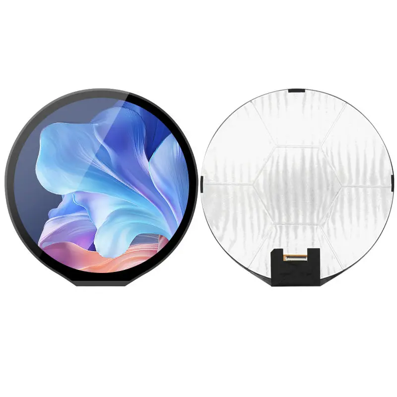
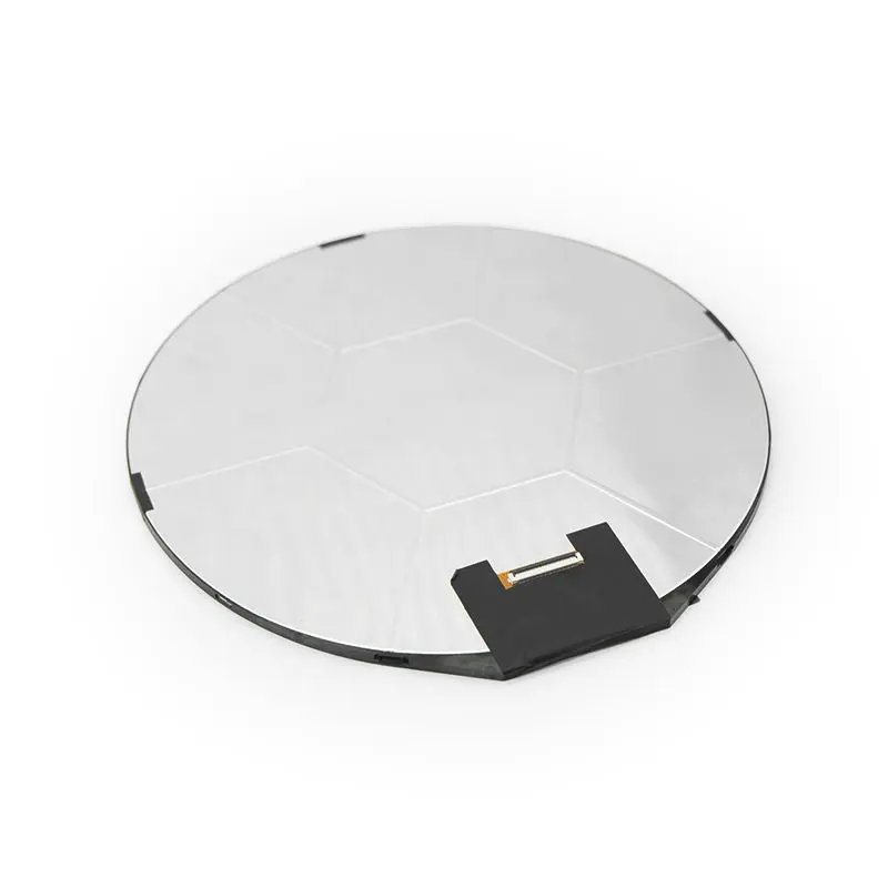
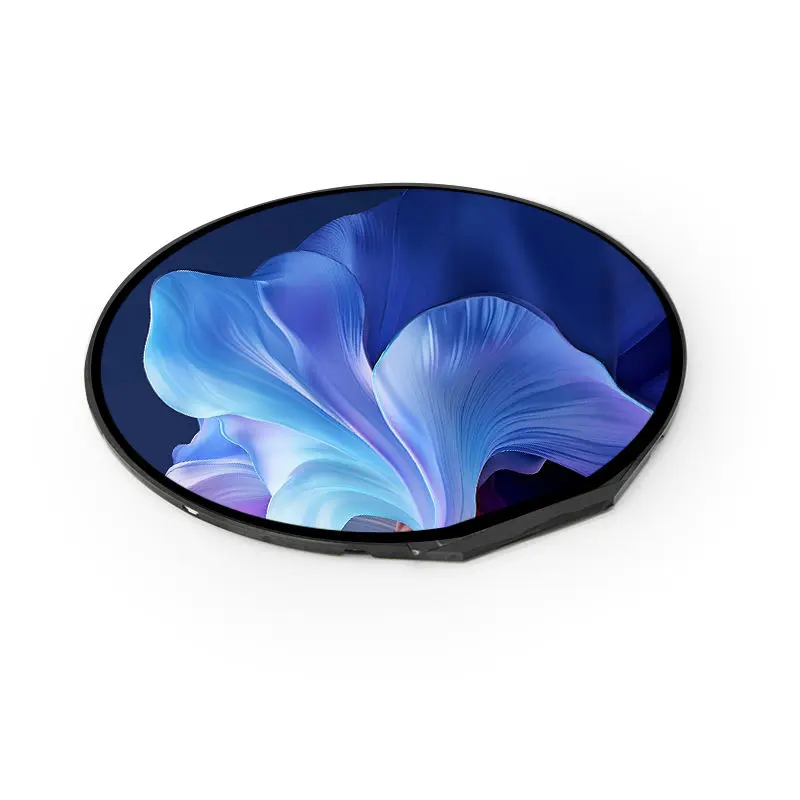
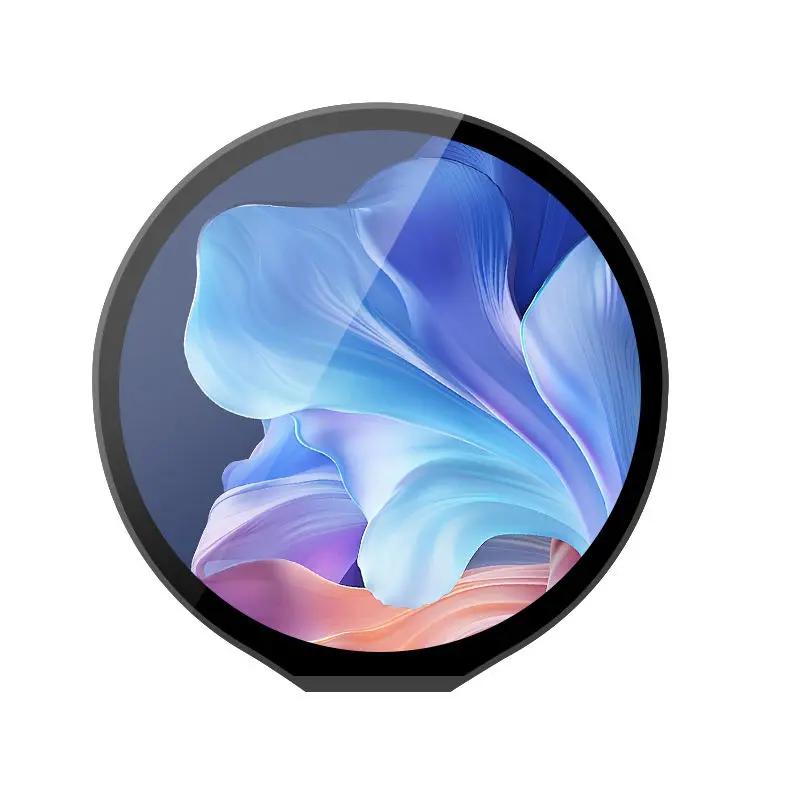
The 8 Inch Round HMI LCD Panel provides a true circular viewing area with a 1080 × 1080 pixel canvas for industrial instruments, control consoles, smart equipment, and embedded interfaces. Its IPS construction, MIPI connection, 208.1 × 208.1 mm active area, and 4.0 mm module thickness support products where the circular display is a defining part of the user interface.
The LCD must be qualified as a complete electrical and mechanical component. Native timing, MIPI lane configuration, operating mode, initialization requirements, power rails, backlight controls, FPC assignment, and enclosure dimensions require approval before hardware release.
Product Summary
This circular IPS TFT panel is designed for user interfaces that benefit from centered controls, radial menus, instrument graphics, circular progress indicators, and status rings.
The native pixel matrix is 1080 × 1080, creating a 1:1 digital canvas behind the round visible area. This supports detailed icons, smooth dial graphics, fine text, and layered operating information without forcing circular content into a low-resolution display.
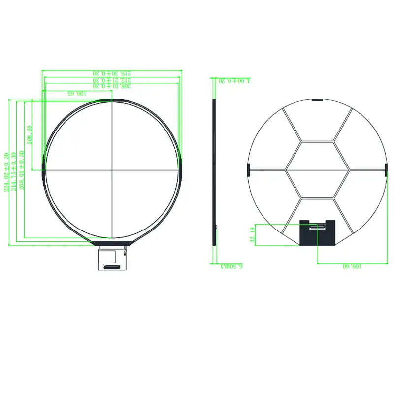
The active display area measures 208.1 × 208.1 mm. The complete module outline is 219.3 × 224.02 × 4.0 mm, including the non-circular lower region required for the FPC and module structure.
The panel uses MIPI rather than the conflicting LVDS wording in the marketplace title. Touch is not confirmed as part of the standard assembly.
Product Main Parameters
| Main parameter | Confirmed specification |
|---|---|
| Display size | 8 inches |
| Display geometry | Circular |
| Native resolution | 1080 × 1080 pixels |
| Pixel canvas | 1:1 |
| Panel technology | IPS TFT LCD |
| Interface | MIPI |
| Active area | 208.1 × 208.1 mm |
| Module outline | 219.3 × 224.02 × 4.0 mm |
| Pixel pitch | 192.6 × 192.6 μm |
| Brightness | 300 cd/m² |
| Contrast ratio | 1000:1 typical |
| Viewing angle | 85°/85°/85°/85° |
| Display colors | 16.7M colors |
| Driver identifier | FT8006S-AA |
| Touch status | Not confirmed as standard |
Circular UI Design with a 1080 × 1080 Canvas
Preparing a 1:1 Interface Layout
The host and graphics software should generate a 1080 × 1080 square frame. The visible circular area is then positioned within that square pixel canvas.
Important interface elements should remain inside a circular safe area, including:
- numeric readings;
- alert messages;
- navigation labels;
- touch targets when touch is added;
- brand marks;
- status icons;
- scale markings;
- operating instructions.
Content placed near the corners of the square frame may not be visible within the circular active area.
A square source canvas should not be confused with a square physical panel. The visible display is circular, while the digital frame remains 1080 × 1080 pixels.
Using Radial Controls and Status Graphics
The round geometry is well suited to:
- dial-style indicators;
- rotary control menus;
- compass layouts;
- progress rings;
- speed or process gauges;
- centered equipment states;
- segmented alarm zones;
- circular navigation wheels.
Radial elements should be tested at the final viewing distance. Very fine scale marks may be technically sharp but difficult to read when the display is installed behind a cover lens or viewed from a distance.
The 1080 × 1080 resolution provides substantial detail, but interface legibility still depends on font size, line thickness, contrast, animation speed, and ambient lighting.
MIPI Integration for the 8 Inch Round HMI LCD Panel
Host Timing and Lane Qualification
A matching MIPI connector does not guarantee electrical compatibility.
The engineering review should confirm:
- MIPI DSI lane count;
- per-lane data rate;
- command mode or video mode;
- native 1080 × 1080 timing;
- horizontal and vertical blanking;
- color format;
- panel supply rails;
- reset and enable signals;
- initialization commands;
- sleep and wake behavior;
- backlight enable and dimming.
MIPI DSI is widely used for embedded circular displays, but lane count, initialization, timing, and controller support remain model-specific. Comparable high-resolution round displays are marketed with MIPI interfaces for embedded and HMI applications.
The detailed interface package must be approved before PCB layout or firmware completion.
FPC and Pin-Assignment Review
The model suffix contains -40, but this does not provide sufficient evidence to publish a confirmed 40-pin connector.
Request an approved connector table showing:
- total pin count;
- connector pitch;
- pin-1 location;
- contact side;
- FPC insertion direction;
- MIPI lane assignment;
- clock lane;
- power rails;
- ground distribution;
- reset and control signals;
- backlight connections;
- test points.
A mechanically compatible connector may still use a different voltage, signal order, lane mapping, or contact orientation.
FT8006S-AA Documentation Boundary
FT8006S-AA is identified in the technical information.
The identifier alone does not prove:
- the complete initialization sequence;
- required register values;
- MIPI lane count;
- command or video mode;
- host-driver availability;
- power sequencing;
- sleep and wake commands;
- supported frame rates.
The ordered module should include the approved driver documentation, timing table, initialization package, and connector definition.
IPS Optical Performance
300 cd/m² Indoor Readability
The panel luminance is 300 cd/m². This is suitable for evaluation in indoor instruments, equipment consoles, smart-appliance controls, and controlled-light operator interfaces.
It should not be presented as a sunlight-readable or outdoor display.
Finished readability depends on:
- ambient-light level;
- front-cover transmission;
- surface reflections;
- optical bonding or air gap;
- installation angle;
- enclosure recess;
- interface color choices;
- font and icon contrast.
The completed display stack should be tested in the final enclosure under the intended lighting.
Full-View Installation Planning
The panel is specified with 85° viewing in four directions. This supports interfaces that may be viewed from several normal positions around a machine or instrument.
The viewing specification does not remove the need to review:
- installation height;
- operator approach direction;
- display tilt;
- cover-lens reflection;
- nearby lighting;
- circular content alignment;
- mechanical centering.
A visually centered circular UI requires both accurate graphics positioning and accurate panel alignment within the enclosure.
Mechanical Integration and Enclosure Control
The active area is 208.1 × 208.1 mm, while the complete module measures 219.3 × 224.02 × 4.0 mm.
The module is not a perfect circular disc because its electronics and FPC require additional structure below the active area.
The approved drawing should control:
- visible opening diameter;
- module outline;
- active-area center;
- FPC exit;
- lower electronics extension;
- rear-component height;
- connector access;
- support locations;
- pressure-free zones;
- tolerance stack;
- cover-lens clearance.
The enclosure should not apply concentrated force to the active glass, border, FPC, or rear components.
A round cosmetic opening must be aligned with the active-area center rather than the overall rectangular drawing boundary.
Recommended Application Routes
The panel may be evaluated for:
- industrial instrument displays;
- machine control consoles;
- circular operator interfaces;
- smart-appliance control panels;
- marine-style gauge interfaces;
- laboratory equipment;
- diagnostic equipment interfaces;
- branded embedded terminals;
- circular information displays.
These are integration routes rather than qualification claims.
Final suitability depends on MIPI compatibility, optical performance, mechanical fit, backlight power, environmental testing, and approved documentation.
Customization and Sample Qualification
Project-specific review may cover:
- FPC shape and material;
- connector and pin definition;
- backlight configuration;
- cover-lens geometry;
- printed border;
- optical bonding;
- touch or non-touch construction;
- touch-controller interface;
- mechanical adaptation;
- packaging;
- controller-board matching.
Custom configurations are generally reviewed from 500 pieces, subject to tooling requirements, material availability, and the requested specification. Sample and standard-module quantities are confirmed separately.
A representative sample should be tested for:
- native 1080 × 1080 output;
- circular content alignment;
- MIPI link stability;
- initialization and wake behavior;
- image orientation;
- color output;
- luminance;
- viewing performance;
- enclosure fit;
- FPC alignment;
- backlight behavior.
Procurement Checklist
Provide the following before sample or production approval:
- native 1080 × 1080 timing;
- MIPI DSI lane count;
- command-mode or video-mode requirement;
- lane data rate;
- color format;
- complete FPC pin assignment;
- connector pitch and contact side;
- panel supply rails;
- reset and enable requirements;
- initialization sequence;
- backlight voltage and current;
- dimming method;
- approved mechanical drawing;
- active-area center position;
- cover-lens requirement;
- touch or non-touch selection;
- target lighting;
- operating environment;
- sample quantity;
- annual demand;
- validation requirements;
- production schedule.
FAQ
About 8 Inch Round HMI LCD Panel
What must be checked before connecting this panel to a MIPI host?
How should graphics be prepared for the circular active area?
Is 300 cd/m² sufficient for an industrial instrument?
What does the FT8006S-AA designation confirm?
Which drawing details must be approved before enclosure tooling?
Freya Yang
+86 18318948097