~
~
~
~
~
~
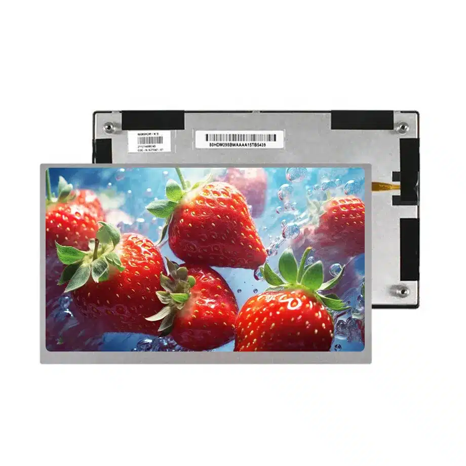
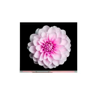
AV080HDB-N19 FOG Vehicle TFT Display Cell BOE
Model P/N
Size
Resolution
Brightness
Viewing Angle
Connector Type
Operating Temp
Overall(mm)
boe
AV080HDB-N19
Brand
Panel Size (inch)
Model P/N
Resolution
Viewing Angle
Contrast Ratio
Response Time
Overall (mm)
Active Area (mm)
Refresh Rate
Display Colors
Panel Type
Connector Type
Surface Treatment
Operating Temp
Touchscreen Type
Storage Temp
Work Mode
Pixel Format
Input Voltage (V)
Vibration Resistance
Designed For
Product Details
Product Overview
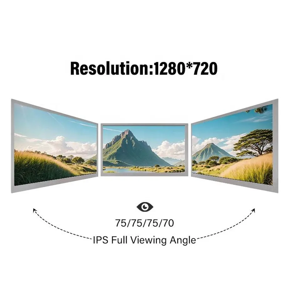
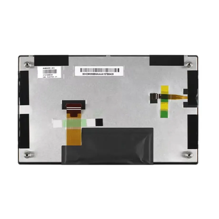
AV080HDB-N19 FOG Vehicle TFT Display Cell is an 8.0-inch BOE a-Si TFT-LCD cell for automotive display integration, supplied as a FOG cell without a backlight or touch screen. Its native image format is 1280(RGB)×720 WXGA at 16:9, with a 176.64 × 99.36 mm active area inside a 185.22 × 110.56 × 1.24 mm outline. The ADS normally-black transmissive cell is specified at 900:1 typical contrast, 85/85/85/85 typical viewing-angle values at CR≥10, 16.7M colors with 72% NTSC wording, hard coating and 3.0% typical transmissivity with polarizer.
The panel runs at 60 Hz and uses single-channel 8-bit LVDS on a 30-pin 0.5 mm FPC, with 3.3 V typical input. Because the product is a bare display cell, the 0 cd/m² brightness entry should not be read as a finished-display luminance target; the host assembly must provide the optical stack and backlight needed to create visible luminance. The operating range is -30 to 85 °C, storage is -40 to 85 °C, and the model carries a 3.0G vibration reference. Those are component specifications for qualification, not a claim of any named automotive certification or vehicle-platform approval.
Three Core Buyer Value Propositions
1. A bare automotive cell lets the system team control the backlight and optical stack
The FOG construction separates the LCD cell from a finished backlight module, giving integrators freedom to design illumination, thermal spreading, optical films and enclosure depth around the vehicle program. That freedom comes with additional engineering responsibility. The 3.0% typical transmissivity, polarizer, hard-coated surface and 900:1 contrast need to be evaluated together with the chosen backlight, diffuser stack and cover lens. A complete display module cannot be specified from the cell's electrical and optical data alone.
2. Single-channel LVDS and a 30-pin FPC create a well-defined controller boundary
The native interface is one-channel 8-bit LVDS, not eDP or MIPI, and the cell terminates on a 30-pin 0.5 mm FPC. That narrows controller-board selection and cable design. The production system still needs the exact pin map, pixel-clock timing, power sequence and grounding plan. A controller advertised as “LVDS compatible” is only a starting point because channel mapping, bit ordering and timing assumptions can differ between panels.
3. Wide component temperature and vibration data support vehicle-display qualification planning
The -30 to 85 °C operating range, -40 to 85 °C storage range and 3.0G vibration reference provide useful boundaries for environmental test planning. They do not prove compliance with a vehicle OEM specification, AEC qualification, functional-safety requirement or complete-system vibration standard. Procurement and engineering teams should use them as component-level inputs, then validate the actual backlight, controller, bonding, housing and cable under the target vehicle environment.
Key Specifications at a Glance
| Parameter | Confirmed value |
|---|---|
| Manufacturer / model | BOE AV080HDB-N19 |
| Display size | 8.0 inch |
| Panel form | a-Si TFT-LCD, CELL (FOG), no backlight |
| Native resolution | 1280(RGB)×720 WXGA, 16:9 |
| Active area | 176.64 × 99.36 mm |
| Outline | 185.22 × 110.56 × 1.24 mm |
| Display mode | ADS, Normally Black, Transmissive |
| Contrast ratio | 900:1 typical |
| Viewing-angle values | 85/85/85/85 typical at CR≥10 |
| Response time | 35 ms maximum Tr+Td |
| Colors | 16.7M, 72% NTSC |
| Surface / transmissivity | Hard coating; 3.0% typical with polarizer |
| Refresh rate | 60 Hz |
| Native interface | LVDS, 1 channel, 8-bit |
| Connector | 30-pin 0.5 mm FPC |
| Panel input | 3.3 V typical |
| Touch | Without touch screen |
| Operating / storage | -30 to 85 °C / -40 to 85 °C |
| Vibration reference | 3.0G (29.4 m/s²) |
Why the external backlight is a primary design decision
AV080HDB-N19 FOG Vehicle TFT Display Cell does not contain its own light source. The backlight must therefore be treated as a separate subsystem with its own LED string, driver, thermal path, dimming strategy and optical films. The cell's 3.0% typical transmissivity helps explain why backlight efficiency matters: only a portion of incident light becomes useful transmitted image light after the LCD and polarizer stack. Target display luminance should be defined at the finished assembly, not by assigning a conventional “nit” value to the bare cell.
Backlight design should also consider day/night dimming, minimum usable brightness, PWM or current-dimming behavior, color shift across temperature and local heating behind the cell. A high-brightness automotive display target cannot be claimed from this cell alone. If the system requires sunlight readability, a defined high-ambient contrast ratio or optical bonding, those are additional system requirements that need separate design evidence and validation.
LVDS bring-up: validate the panel timing, not only the connector
Texas Instruments' LVDS training material describes LVDS as a low-voltage differential physical layer and highlights termination, differential signaling and signal-integrity considerations. For this BOE cell, the product-specific facts are one 8-bit LVDS channel, a 30-pin 0.5 mm FPC and a 3.3 V typical panel input. The exact timing table and pin assignment still need to control the production design.
Bench bring-up should cover native 1280×720 timing at 60 Hz, stable clocking, color-bit mapping, cold boot, repeated power cycles and any image reversal functions implemented by the system. Cable routing should be checked in the real vehicle enclosure because ground offset, EMI sources and harness geometry differ from a short laboratory cable. If a serializer/deserializer link is added elsewhere in the vehicle, distinguish that transport link from the cell-native LVDS interface.
Automotive use does not make every automotive architecture interchangeable
BOE's automotive display overview shows the breadth of in-vehicle display applications, including instrument, center-stack and entertainment displays. That manufacturer portfolio context helps frame the market, but it does not prove that AV080HDB-N19 is approved for a particular cockpit position or vehicle. The exact model should be qualified within the intended assembly and use case.
For a new design, define the required viewing position, ambient-light range, backlight luminance, dimming curve, cover-lens treatment and mechanical support before selecting the rest of the display stack. For replacement work, confirm the original model label, 30-pin pinout, FPC orientation, cell outline and optical construction. An 8-inch 1280×720 cell from another family may have the same visible resolution and still require a different backlight, timing or connector arrangement.
Mechanical and optical integration of a 1.24 mm cell
The 1.24 mm outline depth is a cell-level mechanical value, not a complete display-module thickness. Backlight, reflector, diffuser films, light guide, frame, cover glass and bonding can add substantial depth. The 185.22 × 110.56 mm outer rectangle should be checked separately from the 176.64 × 99.36 mm active image area. Support structures should avoid point loads and torsion on the glass while maintaining the FPC bend radius and connector clearance.
Hard coating protects the front polarizer surface to a degree, but it does not replace cover-lens or environmental protection requirements. If optical bonding is used, verify adhesive compatibility with the polarizer and measure reflection, black level and contrast on the completed assembly. The 72% NTSC wording is a color-gamut indicator, not a calibration guarantee, so finished-display color accuracy should be defined with separate white-point, gamma and color-error targets when needed.
Response time, 60 Hz timing and reverse-display behavior
The response entry is a maximum Tr+Td value of 35. Because Tr+Td is a time quantity, the engineering representation is 35 ms; the numeric value and qualifier remain unchanged. That value describes liquid-crystal transition behavior, not total camera-to-display or control-system latency. At 60 Hz, frame transport, graphics processing, buffering and any vehicle-network video path add their own timing.
The exact-model description also identifies up/down and left/right reverse capability. Treat those functions as panel-drive or system configuration items that require validation with the actual controller. Reverse-display support should not be confused with physical connector reversal. During qualification, verify orientation at startup, after sleep or power cycling, and across any diagnostic or fallback video mode used by the vehicle system.
Application fit and sourcing boundaries
AV080HDB-N19 FOG Vehicle TFT Display Cell is documented for Automotive Display use. A defensible integration scenario is an 8-inch vehicle display assembly in which the system designer intentionally provides the external backlight, controller, cover stack and housing around this exact cell. Its 16:9 WXGA format, wide viewing values, single-channel LVDS and wide component-temperature range make those requirements measurable. No exact fit is claimed for a named instrument cluster, center display, camera monitor or OEM platform.
The cell is supplied without touch. If the finished product needs touch, add a separately qualified sensor, controller and cover stack, then repeat optical and environmental validation because those layers can change reflection, luminance and thickness. Confirm current revision information before volume procurement, and do not treat present stock or production-status listings as a guaranteed lifecycle commitment.
Procurement and validation checklist
- Lock the complete BOE AV080HDB-N19 identity in the BOM and incoming inspection plan.
- Verify the 1280×720 native timing at 60 Hz on the production display controller.
- Confirm single-channel 8-bit LVDS, the 30-pin 0.5 mm FPC and exact pin assignment.
- Design the external backlight around the required finished-display luminance, dimming and thermal limits.
- Use the 3.0% transmissivity and 900:1 contrast as cell-level optical inputs, not finished-display performance guarantees.
- Check the 185.22 × 110.56 × 1.24 mm cell outline and active area against the mechanical stack.
- Validate operation from -30 to 85 °C and the applicable system vibration profile in the production assembly.
- Preserve the 35 ms maximum Tr+Td response qualifier when comparing alternatives.
- Qualify any added touch, cover glass or optical bonding as a separate subsystem.
For AV080HDB-N19 FOG Vehicle TFT Display Cell qualification, provide the controller architecture, LVDS timing and cable plan, backlight concept, cover-stack design, target vehicle environment, optical acceptance limits and required quantity. Exact-model control should remain the basis for release so that the cell, illumination, electronics and mechanics are engineered as one display system.
Recommended: Same Size
(8")
Applications & Value of LCD Panel

- Fast sourcing with in-stock panels & cross-reference alternatives
- Stable supply chain with long-term availability
- Engineering-level support from panel to integration
- Custom solutions: cable, touch & optical bonding
- Strict quality control with IQC / OQC / aging test
- Full traceability system for quality assurance
- Complete technical documentation & drawings
- Compliance support: RoHS & certification files