
~
~
~
~
~
~
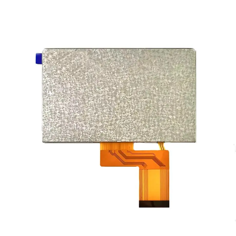
F043A11-401 ODF Full Cell Navigation Display 4.3in Innolux
Model P/N
Size
Resolution
Brightness
Viewing Angle
Connector Type
Operating Temp
Overall(mm)
innolux
F043A11-401
Brand
Panel Size (inch)
Model P/N
Resolution
Viewing Angle
Contrast Ratio
Response Time
Overall (mm)
Active Area (mm)
Refresh Rate
Display Colors
Panel Type
Connector Type
Surface Treatment
Operating Temp
Touchscreen Type
Storage Temp
Work Mode
Pixel Format
Input Voltage (V)
Designed For
Product Details
Cell-Level Product Overview
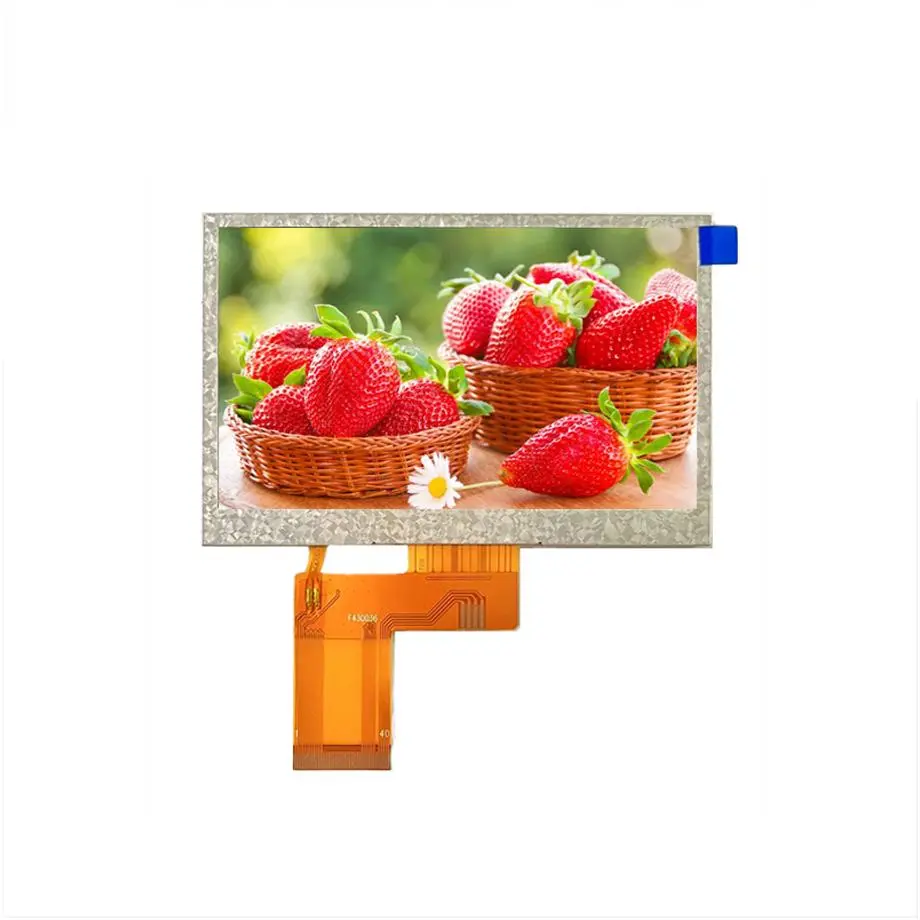
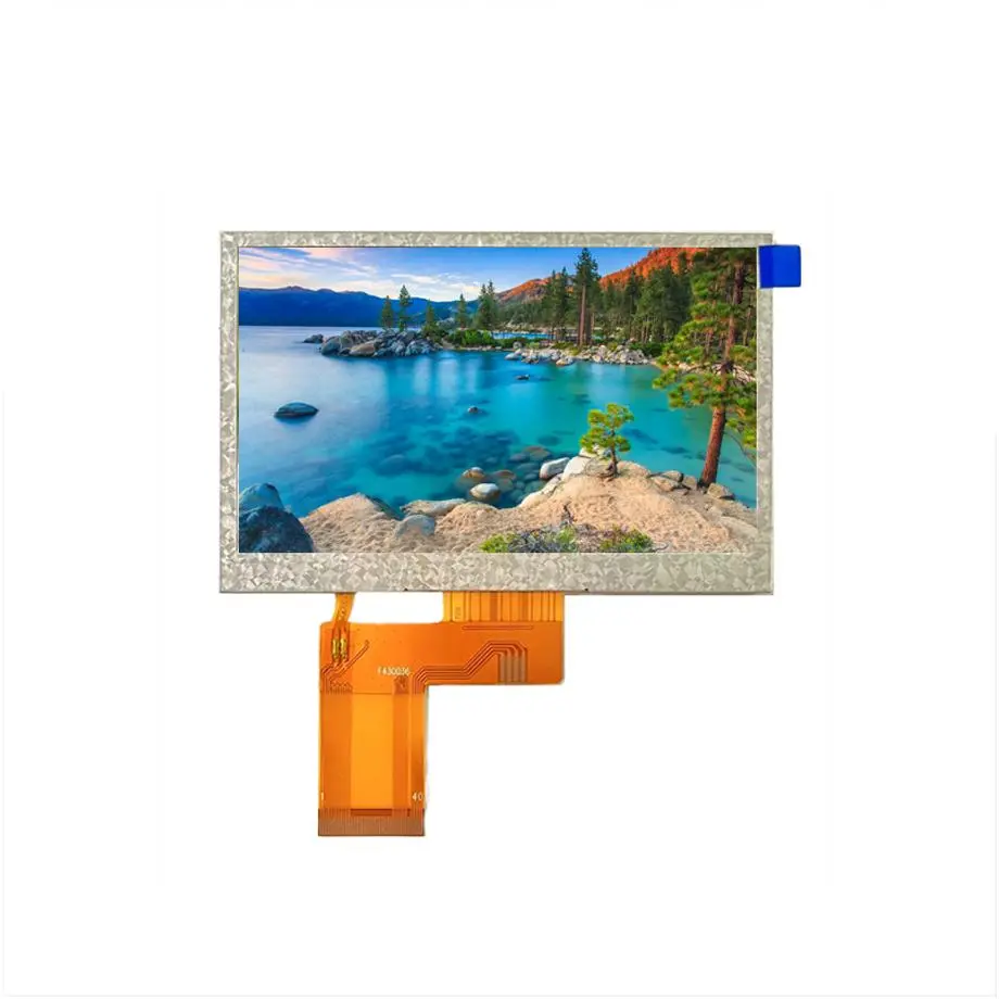
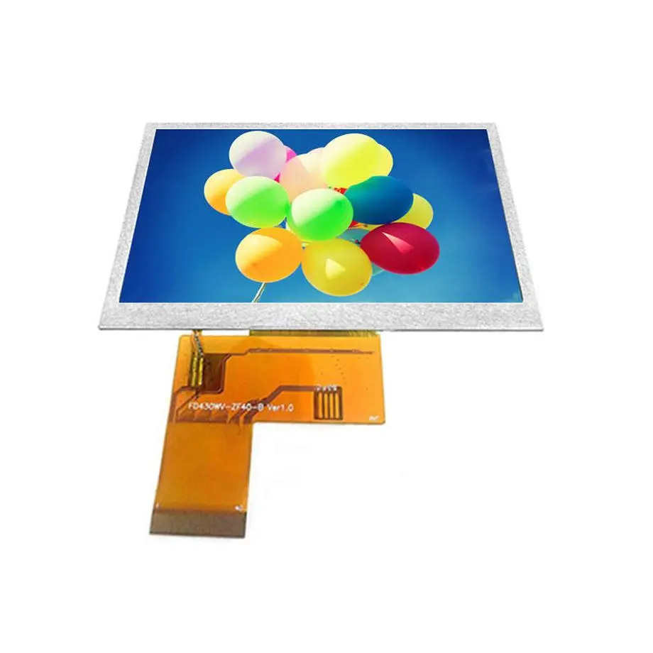
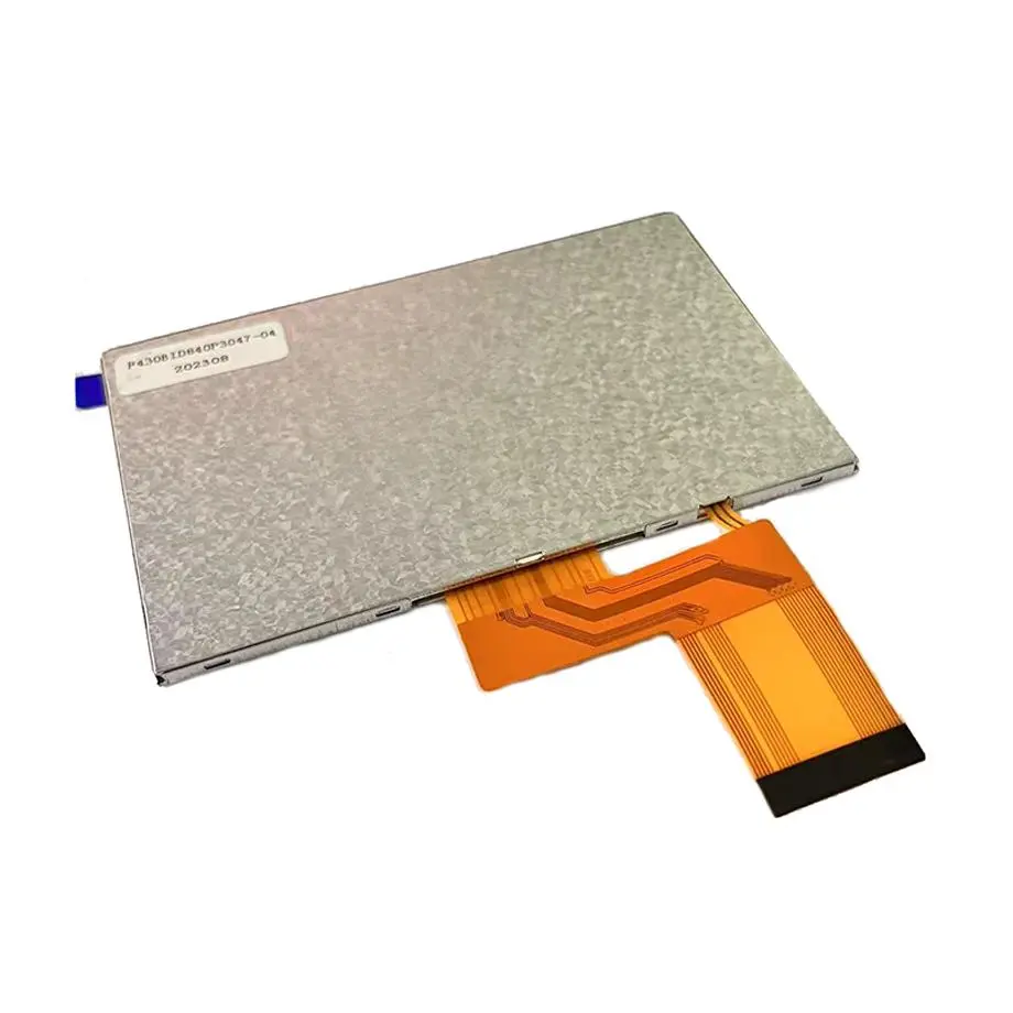
The F043A11-401 ODF Full Cell Navigation Display is a 4.3-inch Innolux a-Si TFT-LCD cell rather than a complete backlit display module. It uses a 480×272 WQVGA raster, RGB vertical-stripe pixel layout and a 95.04 × 53.856 mm active area. The physical cell is 101.7 × 63.5 × 0.8 mm. Because this is a Q-CUT full cell supplied without a backlight and without a polarizer, system designers must treat illumination, polarizer selection, driver integration and mechanical support as separate engineering tasks.
The supplied data lists 0 cd/m² at the cell level, 500:1 typical contrast, 5.41% typical transmittance with polarizer, 16.7 million colors with 52% NTSC, TN normally-white transmissive operation and a -30 to 85 °C operating range. A COG implementation using ST7282 is suggested, but that suggestion does not prove a complete host-interface design or initialization recipe.
Three Core Buyer Value Propositions
- A thin cell platform for custom optical stacks. The 0.8 mm cell depth and lack of integrated backlight/polarizer give an equipment designer more freedom to choose illumination, polarizer and cover construction. That flexibility also increases engineering responsibility because the delivered cell is not a ready-to-use monitor module.
- Wide-temperature screening for compact portable products. The -30 to 85 °C operating range and -40 to 90 °C storage range provide a useful environmental baseline for portable navigation and media-device projects. Finished-product performance still depends on the backlight, polarizer, adhesives, driver electronics and enclosure.
- Driver direction without overclaiming interface compatibility. The exact-model data suggests ST7282 for COG implementation. That helps narrow the controller study, but the native external interface is not established in the supplied facts, so the host architecture must be confirmed from the current Innolux cell and driver documentation.
Key Specifications at a Glance
| Model / maker | Innolux F043A11-401 |
|---|---|
| Product form | 4.3-inch a-Si TFT-LCD Q-CUT full cell |
| Native raster | 480×272 WQVGA, 16:9 |
| Active area | 95.04 × 53.856 mm |
| Cell outline | 101.7 × 63.5 × 0.8 mm |
| Optical construction | Without polarizer; without backlight |
| Transmittance | 5.41% typical with polarizer |
| Environment | -30 to 85 °C operation; -40 to 90 °C storage |
Why does a full cell require more integration work than an LCM?
The F043A11-401 ODF Full Cell Navigation Display does not include the subsystems that make a typical LCM immediately usable. There is no WLED light guide or driver, no finished polarizer stack, and no integrated touch panel. The 0 cd/m² figure is therefore not a statement that the LCD cannot display an image; it reflects the fact that the cell itself has no illumination source. A complete product needs a compatible backlight and optical stack.
Backlight design
Backlight work begins with the active area and optical aperture, not with a guessed LED count. The light guide, diffuser films, reflector, LEDs, thermal path and current driver must be designed as one system. Luminance, uniformity and color temperature should be measured after the cell, polarizers and final cover are assembled. Do not copy LED current or string voltage from another 4.3-inch module.
Polarizer and optical stack
The cell is listed as without polarizer, while transmittance is specified as 5.41% typical with polarizer. That distinction matters: the chosen polarizer pair affects contrast, viewing behavior, brightness and appearance. A custom cover lens or anti-glare film can further change the optical result. Validate the complete stack rather than treating the transmittance number as a finished-product luminance prediction.
Mechanical support
A thin glass cell requires controlled support and assembly pressure. Use the current Innolux drawing for seal area, bonding area, edge clearance and handling limits. The 101.7 × 63.5 mm outline and 0.8 mm cell depth are useful envelope values, but they do not define a bezel, mounting bracket or impact-protection scheme.
How should the ST7282 suggestion be interpreted?
The exact-model information suggests an ST7282 COG driver. That is a component-level direction, not a promise that any board labeled “ST7282” will work without engineering. STMicroelectronics LCD-TFT controller application note provides broader guidance on how pixel timing, framebuffer architecture and LCD-TFT interfaces are handled in embedded systems; it is useful context for system design even though the F043A11-401 cell requires its own exact driver and timing documentation.
Before schematic release, obtain the Innolux cell specification and the applicable Sitronix driver documentation. Confirm source/gate mapping, RGB data format, synchronization mode, clock limits, power rails, reset behavior and any serial configuration path. If a controller board is used between the host and the cell, its input interface is a separate fact from the cell’s native electrical requirements.
Do not infer a native connector
The supplied exact-model data does not establish a standard external connector or a plug-and-play RGB/LVDS/eDP interface. Leave that field unresolved until documentation proves it. A custom FPC, COG bond or board-level interconnect can be specific to the assembled product and should not be invented from the driver name.
Key Specifications
| Display mode | TN, normally white, transmissive |
|---|---|
| Viewing angle | 70/70/50/60 typical at CR≥10; 6 o'clock view direction |
| Contrast | 500:1 typical |
| Response | 25 ms typical Tr+Td |
| Colors | 16.7M; 52% NTSC |
| Surface | Without polarizer |
| Cell plate thickness | 0.40 + 0.40 mm |
| Suggested COG driver | ST7282 |
| Touch | Without |
| Brightness | 0 cd/m² at cell level because no backlight is included |
What do the TN viewing figures mean for UI placement?
The panel lists 70/70/50/60 typical viewing angles at CR≥10 and a 6 o’clock view direction. That asymmetric TN behavior should influence mechanical orientation and UI placement. In a handheld navigation or media product, the designer should test the intended viewing position, tilt range and mounting orientation with actual content. A rotated installation can move the preferred viewing direction away from the user.
The F043A11-401 ODF Full Cell Navigation Display is therefore better evaluated with real interface graphics than with a static white screen. Check text legibility, map colors, icons and video content at the expected eye position. If the product is used by more than one viewer or mounted at an unusual angle, the TN viewing envelope may become a stronger selection factor than nominal resolution.
Where does this 4.3-inch cell fit?
Same-model application references identify portable navigation and MP3/PMP media devices. Those use cases align with the compact 4.3-inch 16:9 format and 480×272 raster. Innolux display-application overview also describes Innolux consumer-electronics applications that include personal navigation devices, providing broader manufacturer context for this type of compact display.
Those application labels should not be stretched into guaranteed fit for a specific GPS, dashboard, handheld terminal or legacy media player. A replacement study must compare active area, outline, cell thickness, viewing direction, driver architecture, optical stack and environmental limits. A similar 4.3-inch WQVGA cell can still differ in bond layout, timing or mechanical edge geometry.
How should brightness be specified for a custom assembly?
Because the cell has no backlight, the correct system brightness target belongs to the finished assembly, not to the bare F043A11-401. Engineering should define a target luminance and uniformity after selecting the LED system and polarizers. Thermal limits, battery power and optical efficiency then determine whether the target is practical.
A useful prototype plan is to build at least one optical stack with the intended light guide, LEDs and polarizers, then measure center luminance, multi-point uniformity, contrast and color at room temperature. Repeat critical measurements at temperature extremes because LED output, polarizer behavior and liquid-crystal response can change with temperature.
What should procurement ask for?
Procurement should request the current Innolux cell drawing, driver/bonding information, timing requirements, handling conditions and any available reliability data. Third-party exact-model references list the model as in production, but that does not establish HS-LCD inventory, guaranteed lead time, MOQ, second-source status or a fixed lifecycle horizon. Confirm commercial status for the actual project date.
Replacement and obsolescence planning
For a legacy portable device, capture the approved cell revision, driver implementation, FPC/bonding drawing, polarizer stack and backlight design. If a future substitute is needed, those artifacts provide a meaningful comparison baseline. Replacing only by diagonal size and resolution is risky because the most important differences may be outside the visible pixel matrix.
Engineering Answers in Brief
F043A11-401 is a full LCD cell, not a complete illuminated LCM, so the system must provide its own backlight and polarizer solution.
The 0 cd/m² cell-level luminance value reflects the absence of an integrated backlight and should not be treated as the achievable luminance of a finished assembly.
ST7282 is a suggested COG driver direction for this cell, but it does not by itself prove host-interface, initialization or board compatibility.
The -30 to 85 °C operating range is a panel-cell specification and does not automatically qualify the completed portable device for any regulated environment.
Procurement Checklist
- Obtain the current Innolux cell drawing and exact driver/bonding documentation.
- Confirm the ST7282 implementation details rather than treating the driver suggestion as a complete interface definition.
- Design and validate the backlight, polarizer and cover stack as a system.
- Check 6 o’clock viewing direction against the real product orientation.
- Validate 480×272 timing, optical performance and response behavior at the required temperatures.
- Freeze the cell revision, optical stack and driver implementation for future replacement comparison.
How should a prototype be released?
Release should follow a cell-to-system validation sequence: first verify the driver and pixel timing, then tune the optical stack, then complete mechanical and environmental testing. The F043A11-401 ODF Full Cell Navigation Display should not be approved from a datasheet comparison alone. A successful prototype demonstrates that the chosen backlight, polarizers, driver, host electronics and enclosure work together at the intended viewing angle and temperature range.
Recommended: Same Size
(4.3")
Applications & Value of LCD Panel

- Fast sourcing with in-stock panels & cross-reference alternatives
- Stable supply chain with long-term availability
- Engineering-level support from panel to integration
- Custom solutions: cable, touch & optical bonding
- Strict quality control with IQC / OQC / aging test
- Full traceability system for quality assurance
- Complete technical documentation & drawings
- Compliance support: RoHS & certification files
