
~
~
~
~
~
~
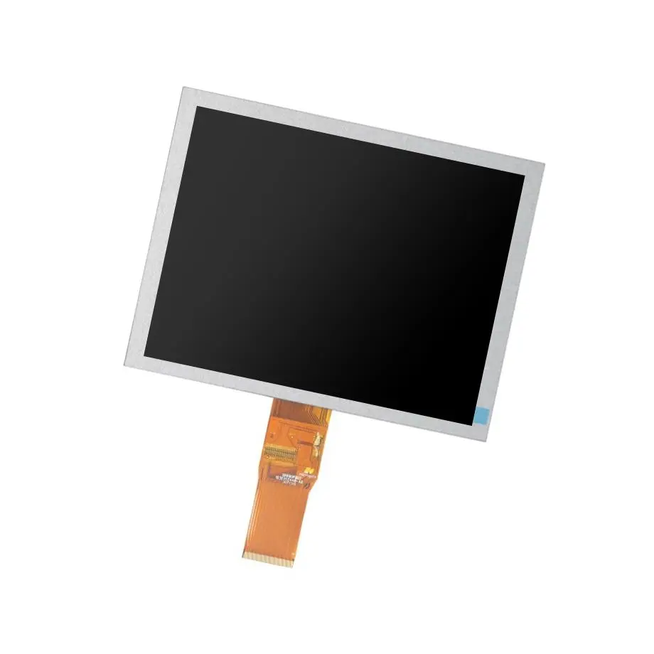
HSD020B2NA-A00 QCIF+ Mobile TN Cell 2.0in HannStar
Model P/N
Size
Resolution
Brightness
Viewing Angle
Connector Type
Operating Temp
Overall(mm)
hannstar
HSD020B2NA-A00
Brand
Panel Size (inch)
Model P/N
Resolution
Viewing Angle
Contrast Ratio
Response Time
Overall (mm)
Active Area (mm)
Refresh Rate
Display Colors
Panel Type
Connector Type
Surface Treatment
Operating Temp
Touchscreen Type
Storage Temp
Work Mode
Pixel Format
Designed For
Product Details
Compact Cell Overview
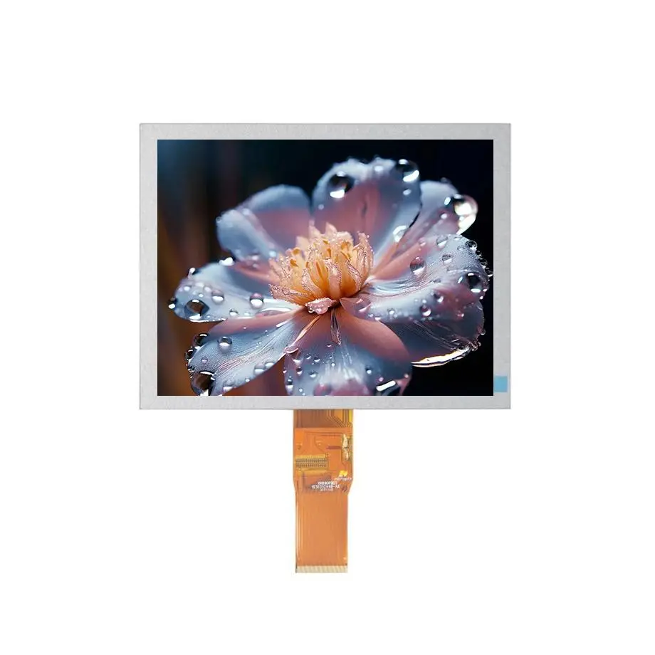
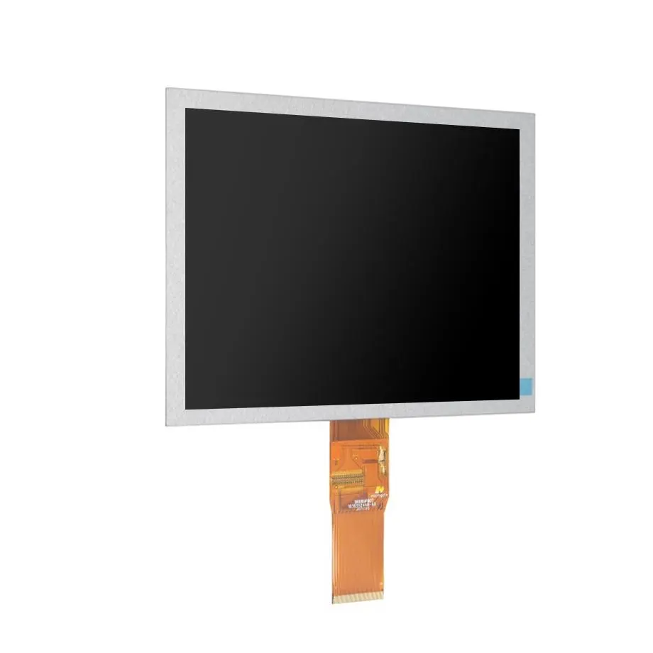
The HSD020B2NA-A00 QCIF+ Mobile TN Cell is a 2.0-inch HannStar a-Si TFT-LCD full cell intended for compact display assemblies rather than use as a finished illuminated module. Its native image is 176×220 in a 4:5 portrait-oriented format, with a 31.68 × 39.6 mm active area inside a 35.1 × 46.2 × 1.0 mm glass-cell envelope. The supplied product facts identify a TN normally-white transmissive structure, RGB vertical-stripe pixels, no integrated backlight, no polarizer and no integrated touch panel.
This distinction matters in engineering and purchasing. A CELL is only one layer of the finished display stack. The mechanical frame, illumination system, polarizers, FPC/COG implementation, cover lens and any touch solution must be defined separately. The 0 cd/m² value in the cell data is therefore not a useful finished-product brightness target; it reflects the absence of an integrated light source.
Three Core Buyer Value Propositions
- Very compact glass envelope for legacy mobile-scale products. The 35.1 × 46.2 mm cell outline and 31.68 × 39.6 mm active area give designers a precise starting envelope for small handheld products. Mechanical release still requires the exact bonding and edge-clearance drawing because glass outline alone does not define an assembled module.
- Known TN viewing orientation for portrait UI placement. The specified 12 o’clock view direction and asymmetric 45/45/45/20 viewing figures help determine how the cell should be oriented relative to the user. The finished viewing result can change after polarizer, cover-lens and enclosure decisions.
- COG driver options exist without forcing a false host-interface claim. The supplied data lists several controller/driver IC suggestions. They narrow the electrical study, but they do not establish a standard connector, RGB bus, MIPI, SPI or other host interface for a completed assembly.
Key Specifications at a Glance
| Model / maker | HannStar HSD020B2NA-A00 |
|---|---|
| Product form | 2.0-inch a-Si TFT-LCD Q-CUT full cell |
| Native raster | 176×220 QCIF+, 4:5 |
| Active area | 31.68 × 39.6 mm |
| Cell outline | 35.1 × 46.2 × 1.0 mm |
| Optical construction | No backlight; no polarizer |
| TN view reference | 45/45/45/20 typical at CR≥10; 12 o'clock |
| Environment | -20 to 70 °C operation; -30 to 80 °C storage |
Why is this not a plug-and-play display module?
The HSD020B2NA-A00 QCIF+ Mobile TN Cell is supplied as a Q-CUT full cell. It does not contain the complete optical and electrical package normally associated with a finished LCM. Engineers must select a compatible backlight, create or source the bonding/FPC implementation, specify polarizers, provide a mechanical carrier and validate any cover glass or touch stack. That work should be planned before quoting a replacement project because the cost and risk reside in the complete stack, not only in the glass cell.
Backlight design starts after the cell
The bare cell lists 0 cd/m² because no backlight is included. A finished luminance target depends on LED selection, light-guide efficiency, diffuser films, polarizer transmission, cell transmittance and drive current. The cell transmittance is listed at 16.0% typical without polarizer, so adding the required polarizer stack will change optical throughput. Do not infer LED count, current, voltage or achievable luminance from a different 2.0-inch module.
Polarizer selection changes the optical result
The supplied surface state is “Without Polarizer.” Polarizer orientation, compensation film and surface treatment affect contrast, brightness, color and viewing angle. The 500:1 typical contrast figure and TN viewing data should therefore be evaluated in the intended optical stack. A clear cover lens may preserve image sharpness but increase reflections; an anti-glare treatment may reduce reflections while affecting contrast and sparkle.
Mechanical handling is a glass-cell problem
The cell thickness is approximately 1.0 mm with a 0.50 + 0.50 mm plate construction. That makes edge support, bonding pressure, shock isolation and assembly cleanliness material design issues. Use controlled fixtures and follow the released HannStar mechanical drawing for seal area and keep-out zones. Do not clamp or bond directly against the visible area.
How should the driver-IC list be used?
The exact-model parameter set lists COG suggestions including HX8340-B, ILI9225-series devices, NT35601, NT39115, OTM2201A, R61503V, S6D0164 and SPFD5406B. Treat these as possible controller directions, not interchangeable drop-in solutions. Different drivers may have different register sets, power rails, RAM architectures, timing expectations and host interfaces.
Himax consumer-electronics display-driver overview shows how display-driver products can integrate source, gate, timing and interface functions for small and medium display applications. That broader engineering context explains why a driver name cannot be translated directly into a finished board interface. For HSD020B2NA-A00, the current model-specific cell documentation should control the bonding map, source/gate connection and electrical sequence.
Host interface remains unresolved at cell level
The supplied exact-model evidence does not establish a standard external connector or native plug-in interface. A completed product might expose a parallel RGB bus, processor-style interface, serial configuration path or another architecture depending on the selected driver and board design. Because those details belong to the chosen assembly, the native connector/interface field remains blank rather than being guessed from the driver list.
Key Specifications
| Pixel layout | RGB Vertical Stripe |
|---|---|
| Contrast | 500:1 typical |
| Response | 2/6 ms typical Tr/Td |
| Transmittance | 16.0% typical without polarizer |
| Colors | 262K, 60% NTSC |
| Cell glass | 0.50 + 0.50 mm |
| Display mode | TN, normally white, transmissive |
| Touch | Without integrated touch |
| Driver direction | COG options are model-specific and must be validated |
What does the 12 o’clock view direction imply?
The cell is specified with a 12 o’clock preferred viewing direction and asymmetric viewing-angle limits of 45/45/45/20 at CR≥10. For a TN panel, inversion and contrast loss can be direction-sensitive. The display should therefore be evaluated in the real mounting orientation, especially if a handheld product is viewed from below, rotated, tilted or placed on a dock.
The HSD020B2NA-A00 QCIF+ Mobile TN Cell is best assessed with real UI graphics, not only a white screen. Use representative icons, text, menus and low-contrast content, then view the assembly through the final cover stack. If the project is a replacement for an older mobile or MP3/PMP device, match the original glass orientation and polarizer direction before assuming the electrical replacement is successful.
Where is the model commonly positioned?
The supplied application data identifies mobile phone and MP3/PMP portable-media use. The same exact model also appears in a current HannStar product portfolio listing as a 2.0-inch 176×220 TN cell with a -20 to 70 °C operating range. HannStar panel portfolio reference provides that distributor-level portfolio context. This supports compact handheld and portable-media positioning without implying compatibility with a specific legacy handset or consumer device.
For a new design, 176×220 is a low-resolution format by current smartphone standards, so the stronger buyer case is usually replacement, legacy-platform support, specialized compact equipment or a design where the UI was already built around the QCIF+ raster. Procurement should identify whether the goal is exact replacement or a redesign; those paths have different qualification work.
How should a legacy replacement be qualified?
Start with the existing assembly, not the diagonal size. Record the original active area, glass outline, driver IC, COG/FPC geometry, polarizer orientation, backlight construction, connector pinout and power sequence. If the original product uses HSD020B2NA-A00 directly, obtain the exact revision and compare it with the proposed sample. If the original uses a module built around the cell, the module maker’s added components may be just as important as the HannStar glass.
Electrical replacement checklist
Confirm source/gate mapping, driver revision, logic levels, timing, reset behavior and frame-memory assumptions. A controller board designed around one suggested driver may not operate another suggested driver without firmware changes. Capture initialization code and known-good waveforms from the existing design where possible.
Optical replacement checklist
Compare polarizers, backlight brightness, uniformity, color temperature and viewing direction. A cell-level transmittance match does not guarantee the same finished luminance. If the legacy product has a colored or smoked cover lens, test the final stack under the original use lighting.
What should procurement request?
Request the latest HannStar drawing and model-specific cell specification, plus the bonding/driver documentation that corresponds to the intended COG implementation. Confirm whether the sample is bare cell only or includes any value-added bonding, FPC, backlight or polarizer work. The third-party exact-model reference currently labels the model in production, but that should not be converted into a guaranteed HS-LCD stock level, MOQ, lead time, second-source status or supply-lifetime commitment.
For an older platform, also ask for sample revision traceability and change-control expectations. A visually identical cell may differ by driver revision, bonding details or process change. The procurement record should tie the approved sample to the drawing revision and any firmware assumptions used during qualification.
Engineering Answers in Brief
HSD020B2NA-A00 is a bare TN LCD cell, so it requires a separate backlight and polarizer stack before it can become an illuminated display.
The exact-model driver list provides COG controller directions but does not prove a standard host connector or universal firmware interface.
The 12 o’clock view direction should be preserved during mechanical design because TN contrast behavior is orientation-dependent.
The -20 to 70 °C operating range is a cell specification and does not qualify a finished product for automotive, medical or outdoor use.
Procurement Checklist
- Confirm exact HannStar model and revision.
- Obtain the released glass outline, seal-area and bonding drawings.
- Verify the chosen driver IC, COG map, initialization sequence and host architecture.
- Define the backlight, polarizer and cover stack separately from the bare cell.
- Match the 12 o’clock viewing orientation to the finished product.
- Validate temperature, optics and mechanical support on the complete assembly.
How should the first article be released?
Build the first article as a complete optical/electrical assembly and test it at the intended orientation. Verify pixel addressing, reset and power-up behavior, then measure luminance, contrast and uniformity after the polarizers and backlight are installed. Repeat viewing checks at the product’s real tilt angles and inspect the glass for stress or edge pressure after enclosure assembly. The HSD020B2NA-A00 QCIF+ Mobile TN Cell should be released only when driver, optics, mechanics and environment have been validated together.
Recommended: Same Size
(2")
Applications & Value of LCD Panel

- Fast sourcing with in-stock panels & cross-reference alternatives
- Stable supply chain with long-term availability
- Engineering-level support from panel to integration
- Custom solutions: cable, touch & optical bonding
- Strict quality control with IQC / OQC / aging test
- Full traceability system for quality assurance
- Complete technical documentation & drawings
- Compliance support: RoHS & certification files
