
~
~
~
~
~
~
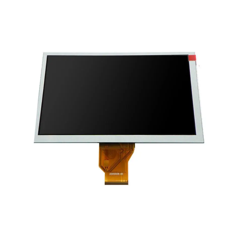
HSD035B7N1-D02 HVGA Portrait Mobile TFT Cell 3.5in HannStar
Model P/N
Size
Resolution
Brightness
Viewing Angle
Connector Type
Operating Temp
Overall(mm)
hannstar
HSD035B7N1-D02
Brand
Panel Size (inch)
Model P/N
Resolution
Viewing Angle
Contrast Ratio
Response Time
Overall (mm)
Active Area (mm)
Refresh Rate
Display Colors
Panel Type
Connector Type
Surface Treatment
Operating Temp
Touchscreen Type
Storage Temp
Work Mode
Pixel Format
Designed For
Product Details
Portrait HVGA Cell Overview
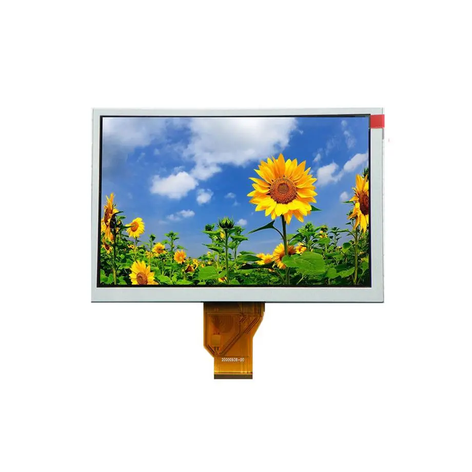
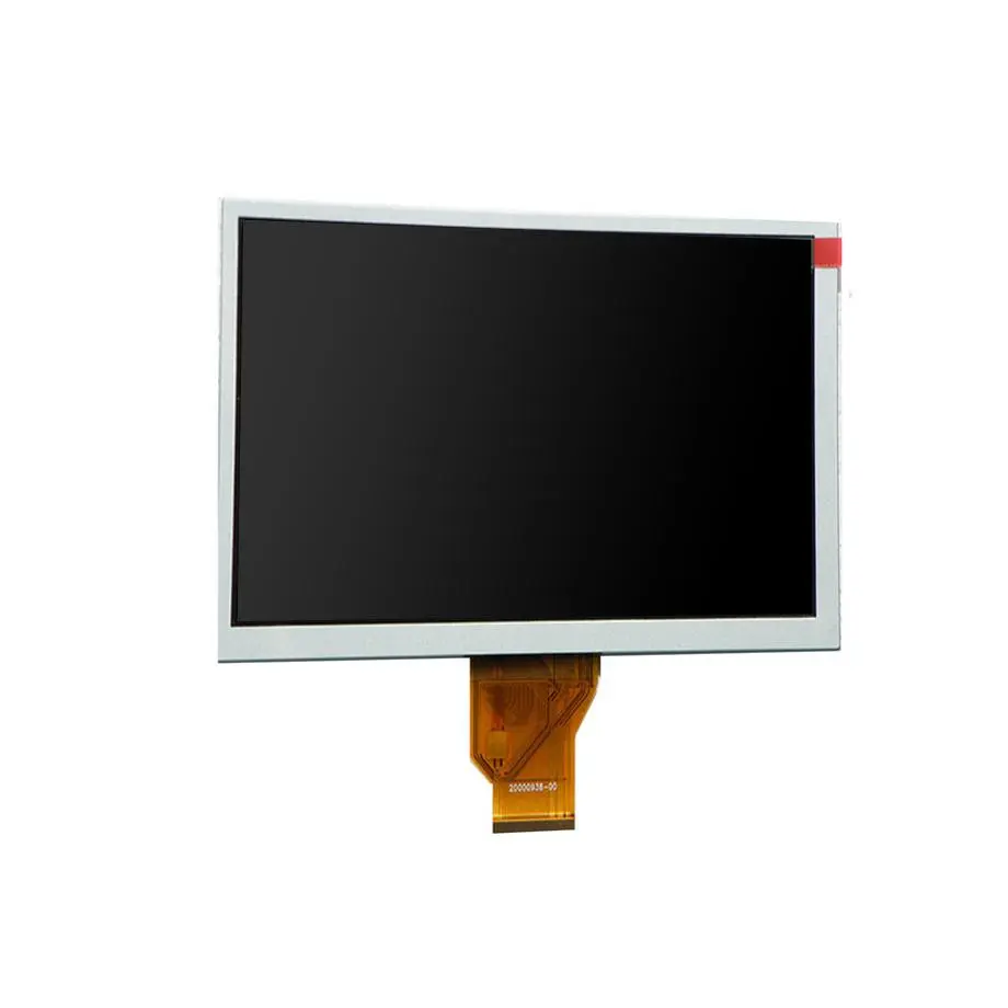
The HSD035B7N1-D02 HVGA Portrait Mobile TFT Cell is a 3.5-inch HannStar full LCD cell built for portrait-oriented display assemblies. It provides a 320×480 HVGA raster across a 48.96 × 73.44 mm display area and uses a 52.96 × 81.34 × 0.8 mm glass outline. The supplied facts identify a TN normally-white transmissive construction, RGB vertical-stripe pixels, 500:1 typical contrast, 262K colors with 60% NTSC and no integrated touch.
This model is not a finished TFT module. It is supplied without polarizer and without backlight, so the integration owner must create the optical stack, select the controller/driver implementation and provide mechanical support. That boundary should be explicit in RFQs because a buyer asking for a “3.5-inch display” may be expecting an LCM with connector and illumination rather than a bare Q-CUT cell.
Three Core Buyer Value Propositions
- Portrait 320×480 geometry for legacy mobile user interfaces. The 2:3 aspect ratio and 48.96 × 73.44 mm image area map naturally to older portrait UI layouts. Replacement success still depends on driver, bonding, polarizer and backlight equivalence.
- Thin 0.8 mm glass-cell construction. The cell creates a compact starting point for custom assemblies where total stack thickness matters. The thin construction requires controlled mechanical support; it is not evidence of a finished rugged or impact-resistant module.
- Driver candidates are documented while system interface remains safely bounded. HX8357-B/C, ILI9486 and R61581 are suggested COG directions. Their presence helps controller research but does not establish a native standard connector or host bus for HSD035B7N1-D02 itself.
Key Specifications at a Glance
| Model | HannStar HSD035B7N1-D02 |
|---|---|
| Form | 3.5-inch portrait a-Si TFT-LCD full cell |
| Image format | 320×480 HVGA, 2:3 |
| Display area | 48.96 × 73.44 mm |
| Glass outline | 52.96 × 81.34 × 0.8 mm |
| Optical baseline | 0 cd/m² bare-cell value; no polarizer/backlight |
| Transmissivity | 14.59% typical without polarizer |
| Temperature | -20 to 70 °C operating; -30 to 80 °C storage |
What must be added to turn the cell into a working display?
The HSD035B7N1-D02 HVGA Portrait Mobile TFT Cell needs a backlight, polarizers, driver/bonding implementation, mechanical carrier and host connection before it behaves like a usable display subsystem. If touch is required, that becomes an additional sensor, cover and controller stack because the exact cell is specified without integrated touch. Each added layer changes thickness, reflection, optical transmission and thermal behavior.
Illumination is a separate design project
The 0 cd/m² bare-cell value should not be used as a finished-display brightness rating. Define the target luminance after the final product use case is known. A handheld device may prioritize battery power; a fixed control panel may prioritize readability. The light guide, LED source, reflector and diffuser films must be matched to the 48.96 × 73.44 mm active region and verified for uniformity.
Transmissivity does not equal luminance
HSD035B7N1-D02 lists 14.59% typical transmissivity without polarizer. That number describes the cell under a specified optical condition; it cannot be converted directly into nits without a complete backlight and polarizer stack. The chosen polarizer pair and cover material can materially change the result. Qualification should use the completed assembly rather than a calculation based on cell transmission alone.
Thin glass needs controlled assembly pressure
The stated 0.40 + 0.40 mm glass construction creates a thin panel. Mechanical fixtures should support the perimeter without twisting the cell or loading the seal. Bonding adhesives, frame tolerances and screw torque should be controlled through the module design. The 52.96 × 81.34 mm glass outline is an envelope, not a finished mounting specification.
How should the COG controller choice be approached?
The supplied cell data suggests HX8357-B, HX8357-C, ILI9486 and R61581. These parts are display-controller directions rather than proof of a single preferred design. The Himax mobile display-driver overview explains the broader role of mobile display drivers, which may integrate source/gate driving, timing, frame memory and power functions. That architecture is why controller selection affects both hardware and firmware.
Before choosing a driver, obtain the exact cell bonding map and confirm source/gate count, pixel format, line/frame timing, gate polarity, voltage requirements and supported driver revision. If the project is repairing an existing product, reusing the original controller can reduce firmware risk, but only when the cell revision and bond layout are proven compatible.
Do not infer MIPI, SPI or RGB from the driver name
The supplied facts leave the external interface blank. That is correct for a bare cell whose final host connection depends on the selected driver and assembly. A controller IC may offer multiple host modes, but those options are not automatically properties of the glass. Public copy should therefore describe the controller decision as an integration requirement instead of inventing a native interface.
Key Specifications
| Display mode | TN, normally white, transmissive |
|---|---|
| Viewing | 70/70/70/60 typical at CR≥10 |
| Preferred view | 12 o'clock |
| Contrast | 500:1 typical |
| Response | 4/12 ms typical Tr/Td |
| Colors | 262K, 60% NTSC |
| Glass depth | 0.40 + 0.40 mm |
| Touch | Without |
| Driver suggestions | HX8357-B/C, ILI9486, R61581 |
What does portrait TN viewing mean for the finished product?
The viewing-angle set is 70/70/70/60 typical at CR≥10 with a 12 o’clock view direction. The asymmetry is important when the cell is installed vertically. Test the product from the expected user eye position, especially if it is held below eye level or tilted on a cradle. TN image inversion can be more noticeable in one direction than another.
The HSD035B7N1-D02 HVGA Portrait Mobile TFT Cell should be tested with actual portrait graphics: menus, numbers, icons, gradients and low-contrast text. If the design rotates the cell 180 degrees, the preferred view direction changes relative to the user. A software rotation can correct image orientation but cannot move the panel’s physical viewing characteristics.
Where is this model used?
The supplied exact-model application field identifies mobile phone use. A current HannStar product portfolio also lists HSD035B7N1-D02 as a 3.5-inch 320×480 TN cell with -20 to 70 °C operation. HannStar panel portfolio reference supports that same-model classification. The public page can therefore position the cell for legacy mobile-device and compact portrait-display integration without claiming fit in a specific handset.
For a new product, the main engineering question is whether a bare legacy-format cell is preferable to a modern integrated LCM. A bare cell can provide flexibility when an existing optical/mechanical stack must be preserved. An integrated module can reduce development work when the enclosure and electronics are being redesigned. Procurement should decide which problem is being solved before comparing unit prices.
How is a replacement different from a redesign?
In an exact replacement, preserve the original driver, bond geometry, polarizer orientation, backlight aperture and glass thickness wherever possible. The objective is to minimize changed variables. In a redesign, those constraints can be reopened, but the project then becomes a new display subsystem qualification rather than a simple part substitution.
Exact-replacement evidence
Record the original HannStar model suffix, drawing revision, COG driver, initialization sequence and any value-added module supplier. Compare physical samples under magnification if the original documentation is incomplete. A 320×480 cell from the same family is not acceptable evidence for this D02 suffix unless the current run establishes exact equivalence.
Redesign evidence
Define target brightness, target viewing angle, touch requirement, host interface, battery or power budget, operating temperature and total stack thickness. Then decide whether HSD035B7N1-D02 remains the right glass platform. Avoid carrying legacy constraints forward merely because the diagonal and raster are familiar.
What should procurement confirm?
Ask for the current HSD035B7N1-D02 cell specification, mechanical drawing and any COG bonding information tied to the proposed sample. Confirm whether the quote is bare glass, COG, FOG or a value-added assembly. The exact-model third-party reference currently reports the model as in production, while component-market listings also show active supplier inventory. Those signals should not be converted into a guaranteed HS-LCD stock level, fixed lead time, MOQ or lifecycle commitment.
Because the response-time source row carried an obviously incompatible “mm” unit, the workflow preserves the user-supplied 4/12 numeric values and normalizes the physical quantity to milliseconds based on the Response Time label. That semantic correction is traceable and does not change the supplied numbers.
Engineering Answers in Brief
HSD035B7N1-D02 is a bare 320×480 TN LCD cell, not an illuminated plug-and-play display module.
The model is supplied without polarizer and backlight, so final luminance must be measured after the optical stack is built.
HX8357-B/C, ILI9486 and R61581 are controller suggestions, not proof of a standard external host interface.
The -20 to 70 °C operating range belongs to the cell and does not establish environmental certification for the finished device.
Procurement Checklist
- Verify the exact D02 suffix and drawing revision.
- Confirm 52.96 × 81.34 × 0.8 mm glass geometry and active area.
- Match driver choice, bond map and firmware initialization.
- Define polarizers and backlight as separate assembly items.
- Validate 12 o’clock viewing orientation in the real enclosure.
- Keep production-status evidence separate from supplier lead-time or lifecycle promises.
How should a prototype be signed off?
First establish stable pixel drive using the approved controller and bond map. Next install the intended polarizers and backlight, then measure uniformity, contrast and brightness. Finally assemble the cell into the mechanical frame and repeat viewing, temperature and cosmetic checks. The HSD035B7N1-D02 HVGA Portrait Mobile TFT Cell should only be released after the glass, optical stack, controller firmware and enclosure have passed as one system.
Recommended: Same Size
(3.5")
Applications & Value of LCD Panel

- Fast sourcing with in-stock panels & cross-reference alternatives
- Stable supply chain with long-term availability
- Engineering-level support from panel to integration
- Custom solutions: cable, touch & optical bonding
- Strict quality control with IQC / OQC / aging test
- Full traceability system for quality assurance
- Complete technical documentation & drawings
- Compliance support: RoHS & certification files
