
~
~
~
~
~
~
LC320DXJ-SRA8 6.14% Transmissive TV Cell Mini-LVDS CSOT
Model P/N
Size
Resolution
Brightness
Viewing Angle
Connector Type
Operating Temp
Overall(mm)
csot
LC320DXJ-SRA8
Brand
Panel Size (inch)
Model P/N
Resolution
Viewing Angle
Contrast Ratio
Response Time
Overall (mm)
Active Area (mm)
Refresh Rate
Display Colors
Panel Type
Connector Type
Surface Treatment
Operating Temp
Touchscreen Type
Storage Temp
Work Mode
Pixel Format
Input Voltage (V)
Weight (g)
Designed For
Product Details
Product Overview
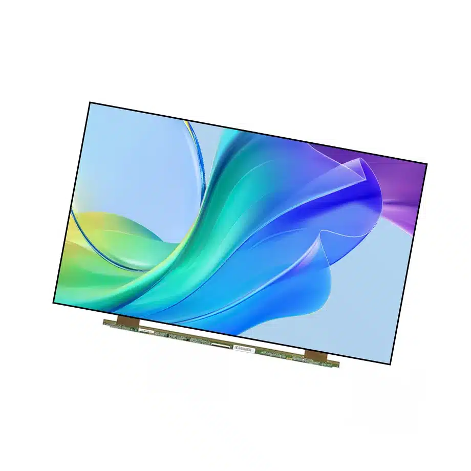
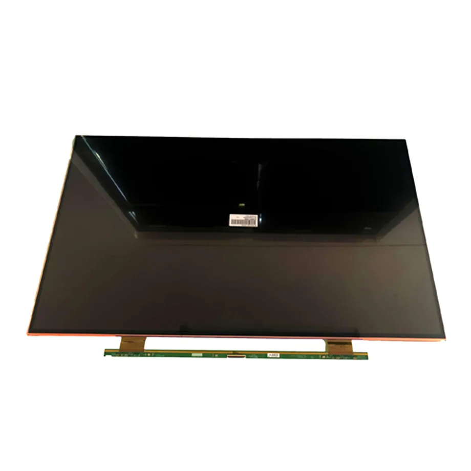
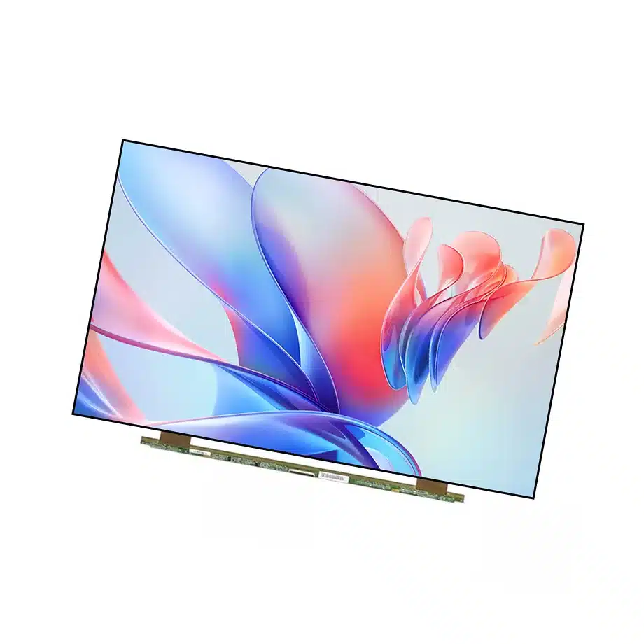
LC320DXJ-SRA8 6.14% Transmissive TV Cell is a 32.0-inch CSOT a-Si TFT-LCD cell intended for television display integration. The panel uses a 1366×768 WXGA 16:9 image, RGB horizontal-stripe pixels and IPS normally-black transmissive operation. Its active area is 697.685 × 392.256 mm, while the glass outline is 715 × 411 × 1.2 mm. Because this is a CELL product supplied without a backlight, the stored luminance is correctly 0 cd/m² and should not be compared with the brightness rating of a finished TV module.
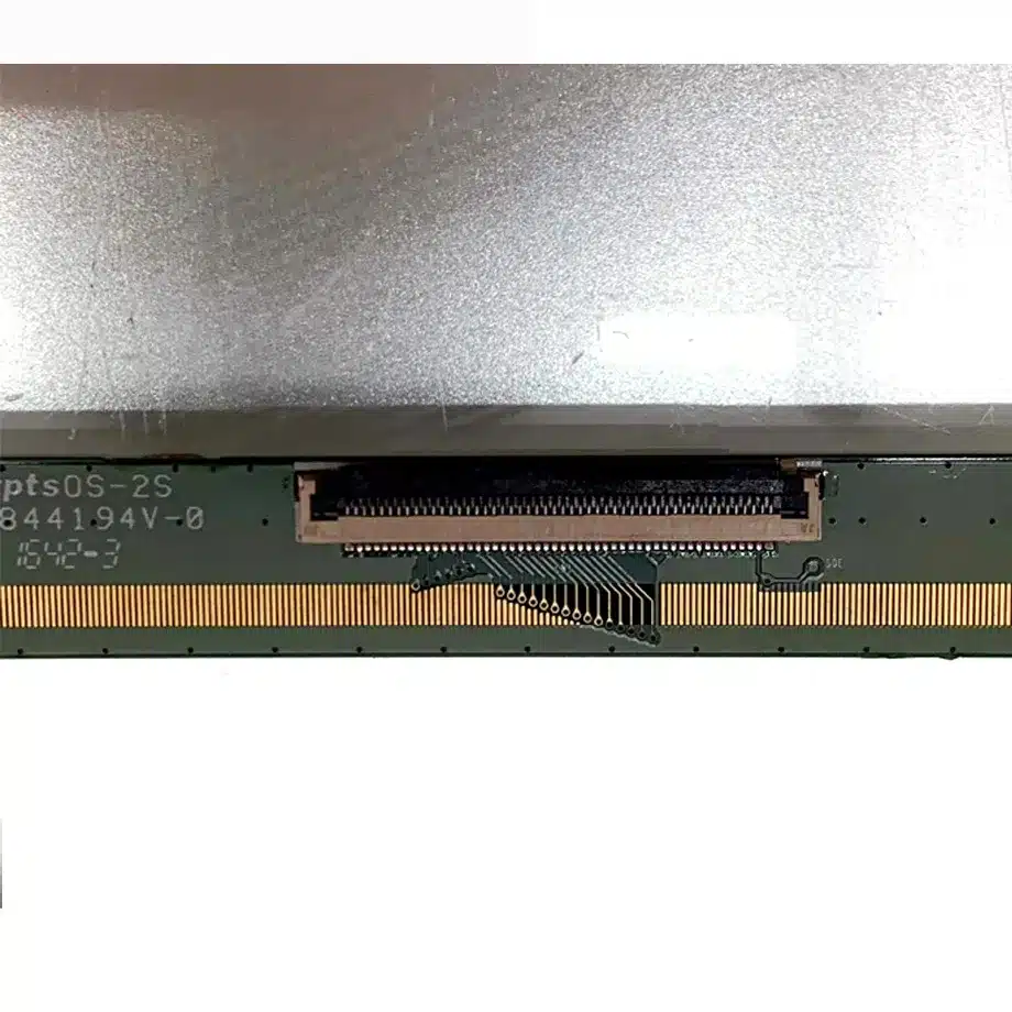
The user-supplied specification confirms 1100:1 typical contrast, 89/89/89/89 minimum viewing at CR≥10, 16.7M colors, 60 Hz refresh and 6.14% typical transmissivity with polarizer. The surface is antiglare with only 1% haze and 3H hard coating. Two source-driver chips are built into the cell, and the native signal path is Mini LVDS through a 50-pin connector with a 12.0 V typical VLCD supply.
Same-model public information lists LC320DXJ-SRA8 as an in-production 32-inch TV cell and confirms Mini LVDS as the panel interface. The exact-model technical listing supports the TV application and cell-only architecture. For differential-link design context, Texas Instruments' LVDS Owner's Manual provides general signal-integrity principles, although the exact Mini LVDS mapping must come from CSOT documentation.
Three Core Buyer Value Propositions
1. 6.14% transmissivity gives the backlight team a concrete optical input
For a cell-only television panel, transmissivity is a more useful design parameter than a finished brightness number. The confirmed 6.14% typical value with polarizer helps the optical team estimate how much light must be generated behind the glass to reach the target TV luminance. It does not determine the final brightness by itself because the LED spectrum, light guide, diffuser stack, reflector, bezel aperture and drive current all contribute to system efficiency.
2. Mini LVDS and built-in source drivers define a clear panel-side electrical boundary
The exact configuration includes two built-in source-driver chips and a 50-pin Mini LVDS connection. That gives the timing-controller and power teams a defined panel-side architecture rather than an undefined bare-glass interface. The connector count alone is not enough for compatibility, however. Pair assignment, clocking, gate/source timing, power sequencing and the 12.0 V VLCD rail must be matched to the exact LC320DXJ-SRA8 documentation.
3. 1% haze preserves a relatively clear front optical appearance
The antiglare surface is specified with only 1% haze and a 3H hard coat. That is materially different from a monitor cell using 25% haze. A lower-haze surface can preserve perceived sharpness and reduce the milky appearance associated with stronger diffusion, but it may also leave more visible reflections. A TV OEM should therefore validate the complete front stack and ambient-light performance rather than assuming “antiglare” means low reflection in every room.
Key Specifications at a Glance
| Parameter | Confirmed value |
|---|---|
| Manufacturer / model | CSOT LC320DXJ-SRA8 |
| Display size | 32.0 inch |
| Panel type | a-Si TFT-LCD CELL, FOB |
| Resolution | 1366×768(RGB), WXGA, 16:9 |
| Pixel structure | RGB Horizontal Stripe |
| Active area | 697.685 × 392.256 mm |
| Outline | 715 × 411 × 1.2 mm |
| Weight | 860 g typical / 900 g maximum |
| Brightness | 0 cd/m² at cell level |
| Contrast | 1100:1 typical |
| Viewing angle | 89/89/89/89 minimum at CR≥10 |
| Response | 7/9 ms typical Tr/Td |
| Transmissivity | 6.14% typical with polarizer |
| Colors | 16.7M |
| Refresh | 60 Hz |
| Interface | Mini LVDS, 50-pin connector |
| Panel supply | 12.0 V typical VLCD |
| Backlight / touch | No backlight / no touch |
| Operating / storage | 0 to 50 °C / -20 to 60 °C |
How Should a TV Backlight Be Designed Around the Cell?
The cell's 6.14% transmissivity and 0 cd/m² luminance make the architecture explicit: the television manufacturer owns the entire illumination system. Start with the required finished-screen brightness and uniformity, then work backward through the cell transmissivity, optical-film efficiency and expected light-guide losses. A television aimed at a dim room and a brighter retail display can use the same LCD cell while requiring very different LED power and thermal designs.
LC320DXJ-SRA8 6.14% Transmissive TV Cell should be tested with the production backlight rather than a temporary light box. Measure center and edge brightness, white uniformity, black level and color after thermal stabilization. The panel's 1100:1 typical contrast is a cell property, but the perceived black level in a finished TV also depends on optical leakage, room reflections and the backlight operating point.
Thermal control matters
LED current and optical-film temperature can change luminance and color over time. A compact chassis that traps heat behind the panel may create brightness drift or accelerated LED aging even though the glass remains within its 0 to 50 °C component range. The complete TV thermal path therefore needs qualification at the intended maximum brightness and ambient condition.
What Must Be Verified on the Mini LVDS Interface?
Mini LVDS is a panel-internal high-speed differential interface rather than a consumer input such as HDMI. A compatible TV design typically uses a timing controller or main-board path that converts system video into the exact panel drive format. Verify the 50-pin assignment, differential-pair mapping, clock relationship, 12.0 V VLCD supply, enable sequence and any panel control signals before applying power.
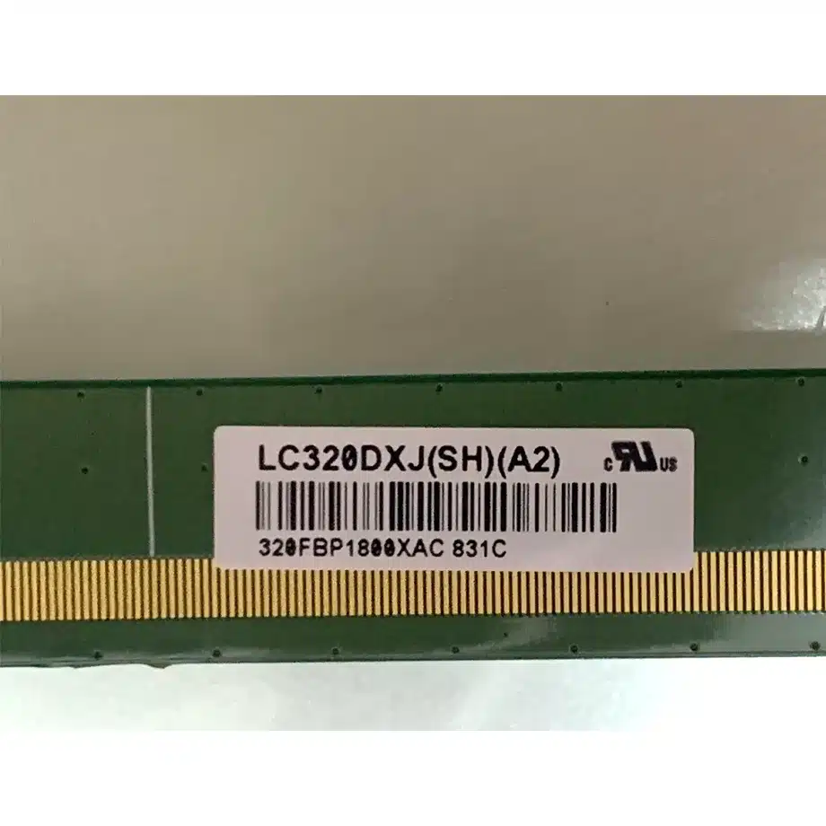
The built-in two-source-chip architecture is useful context, but it does not make another LC320DXJ family model pin-compatible. Similar model names can carry different glass, source-driver or timing details. If a replacement project is involved, compare the exact rear label and source documentation rather than treating “32-inch Mini LVDS” as a universal interface definition.
Why Does 1% Haze Need Front-Stack Testing?
The supplied surface treatment combines antiglare, 1% haze and 3H hardness. A low haze percentage means relatively little scattering, which can help preserve fine text and edge clarity. In a television, however, glare performance also depends on the outer cover, protective films, bezel geometry and ambient light. A cell-only surface measurement cannot predict the complete TV reflection profile.
Prototype evaluation should include dark-scene viewing with room lights, bright-scene viewing near windows and off-axis observation from typical seating positions. The symmetric wide-view specification gives useful panel-level viewing headroom, but the TV's front materials may add reflection or tint that changes the practical experience.
Where Does LC320DXJ-SRA8 Fit Best?
The user-supplied application is TV Sets, and same-model public information independently lists the part as a television cell. LC320DXJ-SRA8 6.14% Transmissive TV Cell therefore fits 32-inch WXGA television platforms, entry-level commercial TV products and custom TV assemblies that already include a suitable timing-controller and backlight architecture. It is not a finished monitor, digital-signage module or drop-in HDMI display.
The 1366×768 native format should also be treated as a system decision. A source device may output 1920×1080 or another resolution, so scaling takes place upstream of the cell. The TV electronics must generate the correct native panel timing and image mapping rather than relying on the cell to perform consumer-input scaling.
How Should Mechanical Integration Be Qualified?
The 697.685 × 392.256 mm active area controls the visible opening, while the 715 × 411 × 1.2 mm outline controls the glass envelope. At 860 g typical and 900 g maximum, the cell also contributes meaningful mass to the chassis. Frame support should distribute load around the glass perimeter and avoid point pressure that can create mura, light leakage or damage.
Because the cell is only 1.2 mm thick, the completed TV structure must provide stiffness. The backlight cavity, metal frame and bezel normally supply this support. Sample builds should be checked after assembly torque, transport handling and thermal cycling so the image is not evaluated only in an unstressed bench fixture.
How Should a First Article Be Approved?
A controlled first article should use the production-intent timing controller, backlight cavity, optical films and chassis rather than a temporary bench setup. First verify the exact model label, 50-pin connector and 12 V VLCD rail. Bring up native 1366×768 timing at 60 Hz, check the image for line defects or link instability, and record the approved TCON firmware and cable. Then install the glass into the final mechanical frame so bezel pressure and support conditions are represented.
After assembly, measure center and corner luminance, uniformity, black level and color at the intended backlight current. Include dark-room and bright-room viewing because the 1% haze surface can behave differently from a stronger matte treatment. The approval record should keep cell-level facts separate from completed-TV results: 6.14% transmissivity, Mini LVDS and 1100:1 contrast are cell properties, while finished brightness, power, color and reflection are system outputs.
Procurement and Qualification Checklist
- Confirm the complete LC320DXJ-SRA8 identity and current CSOT revision.
- Match the exact 50-pin Mini LVDS timing and differential-pair assignment.
- Verify the 12.0 V VLCD rail and documented power-up / power-down sequence.
- Design a separate backlight around the 6.14% typical transmissivity.
- Check the 715 × 411 × 1.2 mm outline and 900 g maximum mass in the chassis.
- Validate the 1% haze surface with the production front stack and room lighting.
- Use the 0 to 50 °C panel range as a component limit, not a finished-TV qualification.
- Confirm current production and change information before volume sourcing.
LC320DXJ-SRA8 6.14% Transmissive TV Cell is a television LCD cell whose strongest engineering facts are its Mini LVDS interface, low-haze surface and known transmissivity. Successful use depends on the OEM's backlight, timing-control, mechanical support and optical validation rather than on treating the cell as a complete display module.
Recommended: Same Size
(32")
Applications & Value of LCD Panel

- Fast sourcing with in-stock panels & cross-reference alternatives
- Stable supply chain with long-term availability
- Engineering-level support from panel to integration
- Custom solutions: cable, touch & optical bonding
- Strict quality control with IQC / OQC / aging test
- Full traceability system for quality assurance
- Complete technical documentation & drawings
- Compliance support: RoHS & certification files
