Freya Yang
+86 18318948097
+852 62667476
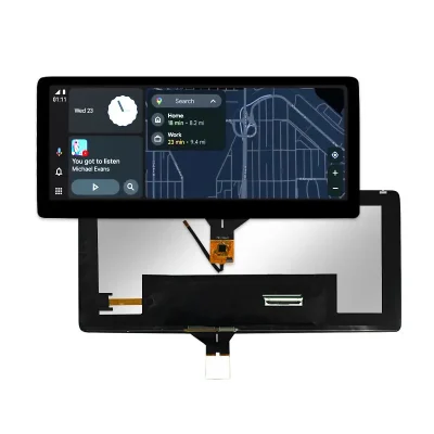
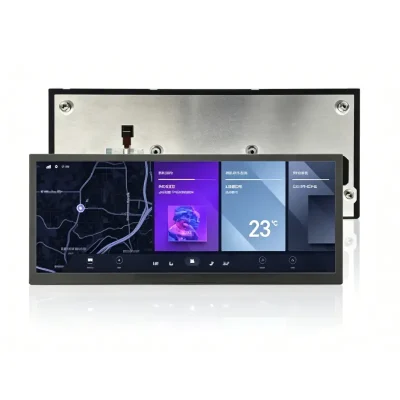
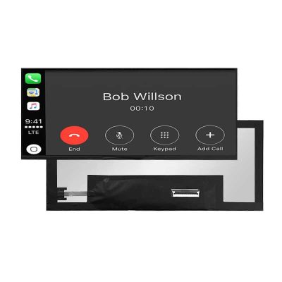
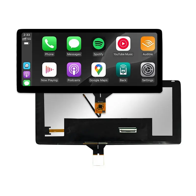
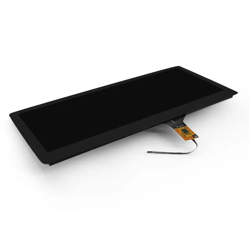
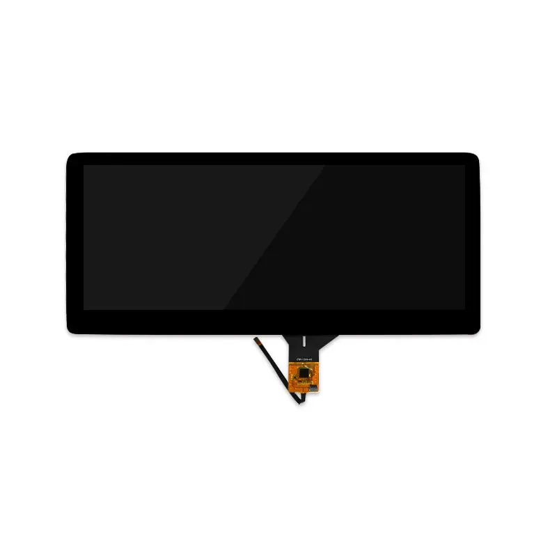
10.25 Inch Panoramic Automotive Dashboard Touch Display Module
Model P/N
Size
Resolution
Brightness
Viewing Angle
Connector Type
Operating Temp
Overall(mm)
huisoar
HS103Z7P-K10-50-V3
Brand
Panel Size (inch)
Model P/N
Resolution
Brightness (nits)
Viewing Angle
Contrast Ratio
Response Time
Overall (mm)
Active Area (mm)
Refresh Rate
Display Colors
Panel Type
Connector Type
Surface Treatment
Operating Temp
Touchscreen Type
Storage Temp
Work Mode
Pixel Format
Protective Glass Specification
Operating Environment
Designed For
10.25 Inch Panoramic Automotive Dashboard Touch Display Module
This wide 1920 × 720 LVDS module combines capacitive touch, 1000-nit luminance, and a 243.648 × 91.368 mm active area for in-vehicle HMI integration.
Product Summary
The Panoramic Automotive Dashboard Touch Display Module provides a 10.25-inch wide-format interface for dashboard, cockpit, instrument, and center-information display projects. Its 1920 × 720 pixel layout supports horizontally structured user interfaces while maintaining a relatively shallow active display height.
The module combines LVDS image signaling with a capacitive touch assembly. It also provides 1000-nit luminance, a Normally Black display mode, 16.7 million colors, and an NTSC 70% minimum color-gamut specification.
The display component should be integrated only after its LVDS timing, voltage levels, connector, pin assignment, touch interface, mechanical drawing, and FPC orientation have been approved against the target controller and enclosure.
Key Specifications at a Glance
| Parameter | Value |
|---|---|
| Display size | 10.25 inch |
| Resolution | 1920 × 720 pixels |
| Active area | 243.648 × 91.368 mm |
| Pixel pitch | 0.1269 × 0.1269 mm |
| Pixel arrangement | RGB vertical stripe |
| Display interface | LVDS |
| Touch technology | Capacitive touch |
| Luminance | 1000 nits |
| Display mode | Normally Black |
| Display colors | 16.7 million colors |
| Color gamut | NTSC 70% minimum |
| Surface treatment | HC |
| Surface hardness | 3H |
| Operating temperature | −30°C to +85°C |
| Storage temperature | −40°C to +95°C |
Why the 1920 × 720 Format Fits Dashboard HMIs
Wide Interface Composition
A 1920 × 720 pixel matrix provides a panoramic canvas for interfaces that place several information groups across one horizontal line. Designers can allocate separate zones for navigation, system status, camera imagery, media controls, vehicle information, or contextual alerts without moving to a conventional tall-format panel.
The 243.648 × 91.368 mm active area also gives enclosure engineers a defined basis for bezel-opening and visible-area planning. The final mask opening should still be coordinated with the approved touch and cover-lens drawings.
Capacitive Touch Integration
The capacitive touch assembly supports a direct front-surface control concept for dashboard HMIs. Its exact controller, communication interface, firmware, touch-point count, cover-lens construction, and operating voltage remain project-confirmation items.
Capacitive touch status alone does not establish USB or I²C compatibility. The touch subsystem must be treated as a separate interface path from the LVDS image connection.
LVDS and Touch-System Integration
Controller Compatibility
LVDS describes the display signal family, but it does not confirm the number of LVDS ports, mapping convention, clock configuration, voltage rails, connector series, pin sequence, or power-control requirements.
An LVDS interface name alone does not guarantee electrical, timing, connector, or pin compatibility with an existing controller.
Before connecting a controller board, compare the complete panel specification, controller output timing, connector drawing, pin assignment, logic-voltage requirements, and backlight-driver requirements. An adapter cable cannot correct incompatible timing or electrical levels by itself.
Touch Interface Confirmation
The image path and touch path should be reviewed independently. A host platform may support the panel’s LVDS video timing but still require a different touch controller, cable, firmware, or operating voltage.
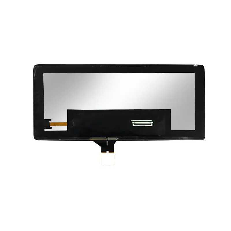
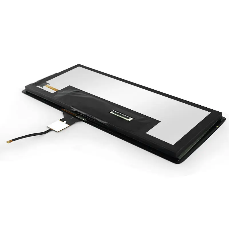
Engineering review should therefore include the touch-interface definition, connector location, FPC direction, cover-lens outline, bonding stack, active touch area, and any required firmware identification.
Panoramic Automotive Dashboard Touch Display Module Optics
1000-Nit Luminance
The 1000-nit specification provides a strong luminance starting point for bright vehicle-cabin conditions. Final perceived brightness depends on the cover lens, touch stack, bonding material, polarizers, surface reflections, dimming strategy, thermal environment, and installation angle.
The 1000-nit luminance rating does not by itself establish sunlight readability after cover glass, bonding, dimming, and thermal conditions are applied.
A complete optical target should define the required luminance at the finished front surface rather than relying only on the bare display value.
Normally Black Image Mode
Normally Black operation supports a dark inactive appearance and can suit dashboard interfaces built around dark backgrounds and illuminated information zones. The supplied data does not establish contrast ratio or directional viewing-angle values, so those parameters should be confirmed during optical qualification.
The HC surface treatment and 3H surface-hardness specification provide useful baseline information for handling and front-surface planning. They do not replace a separate cover-lens abrasion, chemical, impact, or environmental requirement.
Mechanical Integration and Drawing Approval
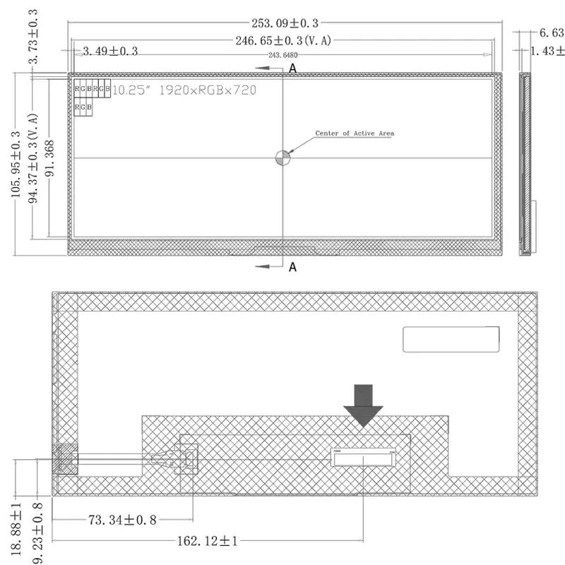
The active area is consistently identified as 243.648 × 91.368 mm, but the available overall-dimension information is not internally consistent.
The tabulated values distinguish configurations with and without PCBA, while the displayed mechanical drawing shows a different outer width, height, and side-profile thickness. The marketplace title also uses an approximately 6.7 mm thickness description.
Mechanical release should use an approved drawing because the tabulated outline and the displayed mechanical drawing contain conflicting dimensions.
Before tooling an enclosure, request a revision-controlled drawing that defines:
- Overall display outline
- Active-area origin
- Bezel opening
- Touch and cover-lens outline
- PCBA envelope
- FPC exit location and bending zone
- Connector position
- Maximum thickness
- Mounting and adhesive areas
- Dimensional tolerances
Environmental and Surface Characteristics
The operating-temperature range is −30°C to +85°C, and the storage-temperature range is −40°C to +95°C. These ranges support evaluation for vehicle-display environments, but they do not establish compliance with a particular automotive reliability, vibration, thermal-cycling, EMC, ESD, or functional-safety standard.
The Panoramic Automotive Dashboard Touch Display Module should therefore be qualified within the complete installed system. The display, touch panel, controller, backlight driver, cables, mechanical supports, cover lens, bonding process, and thermal design can each affect finished-system performance.
Recommended Application Directions
This configuration can be evaluated for:
- Dashboard information displays
- Digital instrument layouts
- Center-information interfaces
- Cockpit control surfaces
- Auxiliary vehicle displays
- Navigation and media HMIs
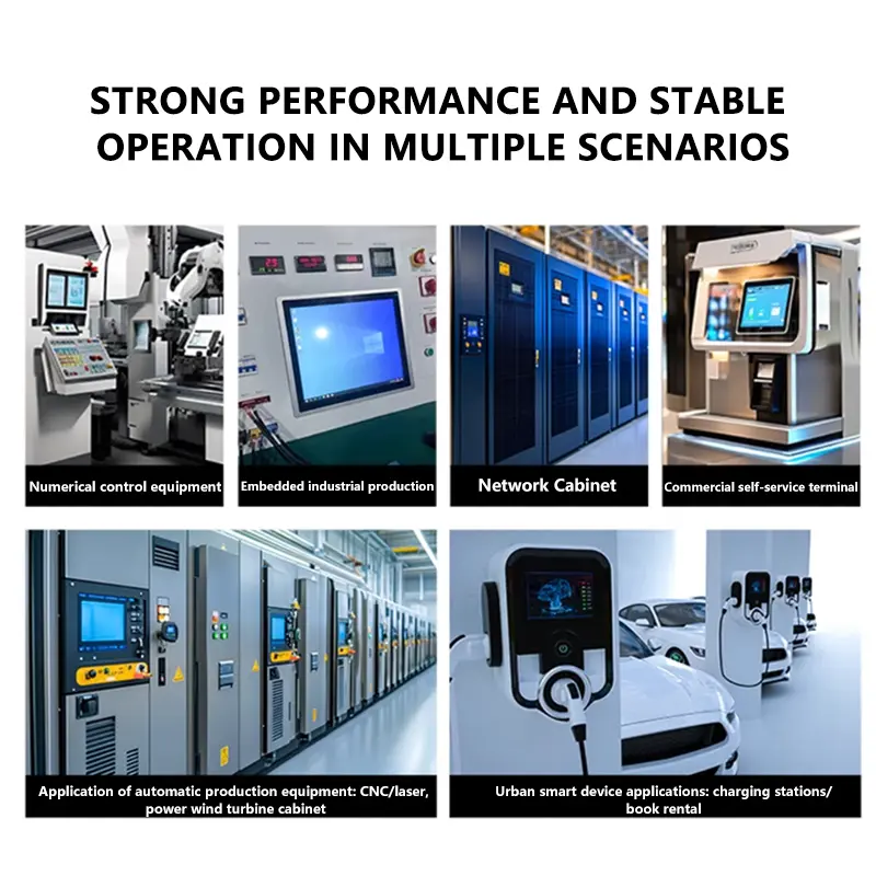
- Transportation-equipment operator interfaces
- Wide-format industrial control interfaces with similar environmental needs
Application approval should be based on the target system specification rather than the application name alone.
Configuration Review
Custom configurations are generally reviewed from 500 pieces, subject to tooling requirements, material availability, and the requested specification. Sample and standard-module quantities are confirmed separately.
Reviewable project items may include:
- Cover-lens outline and printing
- Touch-panel construction
- Touch interface and firmware
- FPC length or orientation
- Connector and pin assignment
- Optical bonding
- Luminance target
- Surface treatment
- PCBA configuration
- Mechanical outline
No customized value should be treated as available until its optical, electrical, mechanical, thermal, lifetime, tooling, and production implications have been evaluated.
Procurement Checklist
Submit the following before sample approval:
- Target application and installation location
- LVDS timing specification
- LVDS mapping and port configuration
- Logic-voltage requirements
- Connector and pin assignment
- Touch-interface requirement
- Controller platform
- FPC direction and permitted bending area
- Enclosure and bezel-opening drawing
- Cover-lens and bonding requirements
- Required finished-surface luminance
- Operating and storage conditions
- Sample quantity
- Forecast annual demand
- Required reliability or compliance standards
FAQ
About 10.25 Inch Panoramic Automotive Dashboard Touch Display Module
What must be checked before connecting this module to an existing LVDS controller?
How should the enclosure be released when the dimension table and drawing differ?
Is the 1000-nit rating sufficient behind an automotive cover lens?
What information is required for a customized touch or interface configuration?
Freya Yang
+86 18318948097