Freya Yang
+86 18318948097
+852 62667476
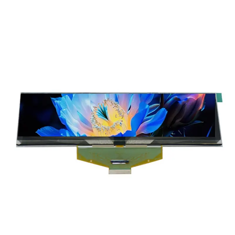
5.5 Inch Bar Type PMOLED Display Module for Instruments
Model P/N
Size
Resolution
Brightness
Viewing Angle
Connector Type
Operating Temp
Overall(mm)
huisoar
HS-5664ASGGFO1
Brand
Panel Size (inch)
Model P/N
Resolution
Brightness (nits)
Viewing Angle
Contrast Ratio
Response Time
Overall (mm)
Active Area (mm)
Refresh Rate
Display Colors
Panel Type
Connector Type
Operating Temp
Touchscreen Type
Storage Temp
Work Mode
Control Type
Weight (g)
Operating Environment
Designed For
5.5 Inch Bar Type PMOLED Display Module for Instruments
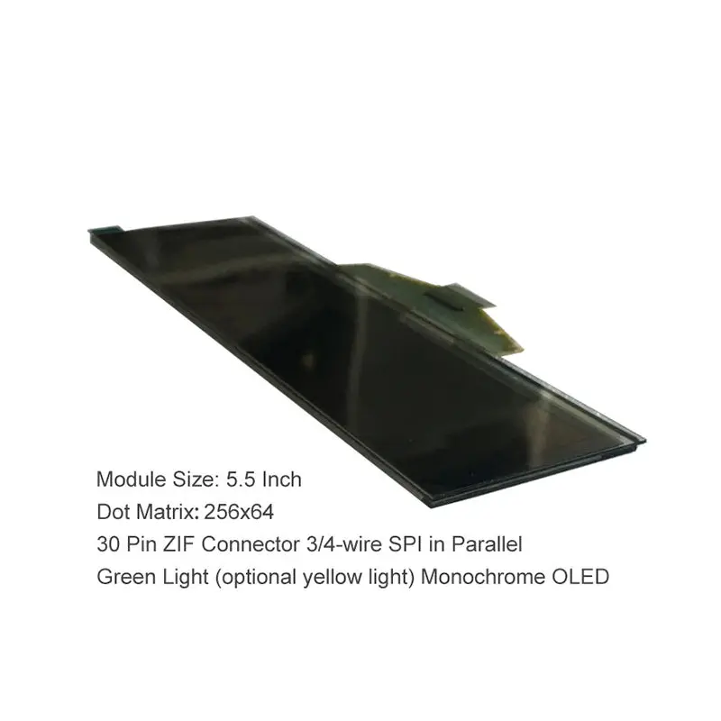
This slim green monochrome OLED panel provides a 256 × 64 information window for status text, symbols and line graphics in narrow equipment front panels.
Product Overview
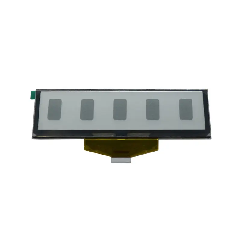
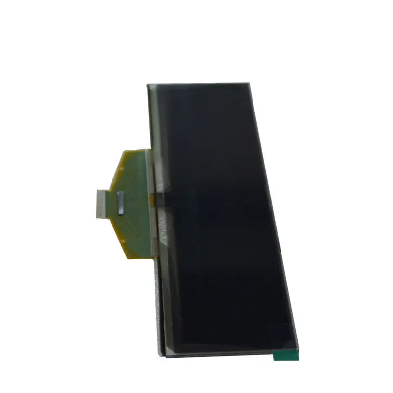
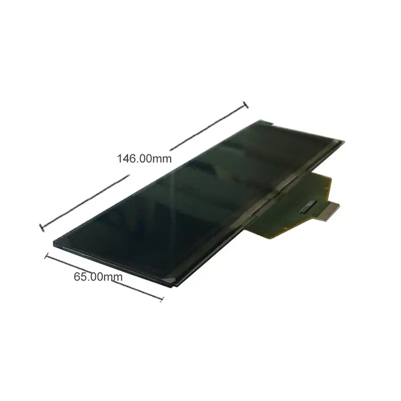
The Bar Type PMOLED Display Module is a long, narrow OLED component for products that need a dedicated information strip rather than a conventional color screen. Its 5.5-inch format combines a 135.65 × 33.89 mm active area with a slim 146 × 45 × 2 mm outline, making it suitable for front panels where horizontal space is available but installation depth is restricted.
The 256 × 64 pixel raster supports text, values, icons, indicators and compact graphical traces. Green monochrome emission keeps the interface visually focused and can provide a clear contrast between active pixels and the dark OLED background.
This module is designed for embedded control rather than direct consumer plug-and-play replacement. The selected interface mode, full 30-pin assignment, power requirements and timing must be approved before hardware release.
Key Specifications at a Glance
| Specification | Confirmed value |
|---|---|
| Display size | 5.5 inch |
| Display technology | PMOLED |
| Matrix type | Passive matrix |
| Resolution | 256 × 64 pixels |
| Standard emission | Green monochrome |
| Active area | 135.65 × 33.89 mm |
| Module outline | 146 × 45 × 2 mm |
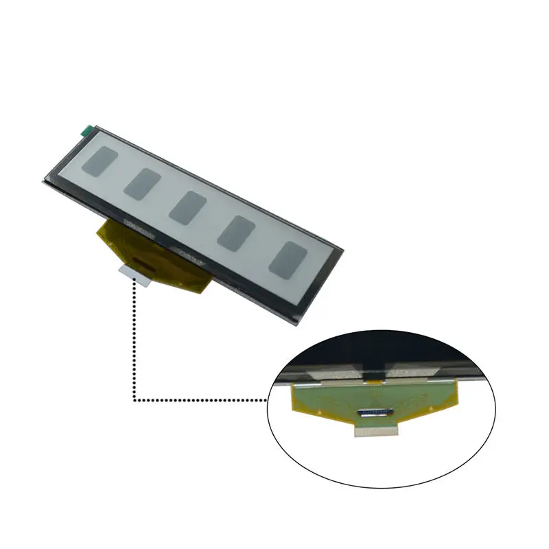
| Connector | 30-pin ZIF |
| Interface options | 3-wire SPI, 4-wire SPI or parallel |
| Drive duty | 1/64 duty |
| Listed weight | 27.1 g |
Bar-Format UI Planning
Organizing a 256 × 64 Information Layout
A 256 × 64 raster is most effective when the content hierarchy is defined around the elongated shape. Rather than shrinking a conventional full-screen interface, designers can divide the panel into horizontal information zones.
Suitable arrangements include:
- one large primary measurement with secondary units;
- two or three compact status rows;
- equipment mode and alarm indicators;
- audio source, track or volume information;
- process values with warning icons;
- communication status and channel data;
- line-style waveform or trend previews;
- menu labels with a highlighted selection;
- machine state and maintenance prompts;
- clock, timer or operating-cycle information.
Font selection should be tested at the native pixel dimensions. A 256-pixel width can support useful text, but long labels may require abbreviations, scrolling or multiple screens.
Green Monochrome Content Priorities
Green is the confirmed standard emission color for this configuration. The interface should therefore use brightness, spacing, symbol shape and pixel patterns rather than color coding to separate information.
Critical states can be differentiated through:
- flashing;
- inverse pixel blocks;
- outlined versus filled symbols;
- larger type;
- warning icons;
- alternating screens;
- increased spacing;
- graphical bars;
- patterned indicators.
Yellow emission may be reviewed as an optional variant, but it should not be assumed interchangeable without confirming the exact optical and electrical specification.
PMOLED Optical and Display Behavior
Self-Emissive Status Presentation
PMOLED pixels emit light directly, so the display does not require a conventional LCD backlight. This enables dark inactive areas and bright monochrome characters in a shallow module structure.
The self-emissive presentation is well suited to information windows where the display should remain visually unobtrusive until text, values or indicators are active. It can be effective in dark equipment bezels, audio front panels and instrument clusters.
Finished readability still depends on the cover structure, ambient light, viewing position and selected drive conditions. Brightness and contrast must be validated from an approved sample because those values are not confirmed for the assigned model.
Appropriate Content Types
The 256 × 64 PMOLED format is suited to:
- text;
- numerical values;
- simple icons;
- progress bars;
- status indicators;
- segmented-style graphics;
- basic menus;
- compact line graphics;
- simplified waveform previews.
It is not intended as a replacement for a full-color TFT when the application requires photographs, video, complex animation or high-density graphical dashboards.
The 256 × 64 raster is intended for text, icons, indicators and compact line graphics rather than full-motion video.
Integrating the Bar Type PMOLED Display Module
Selecting SPI or Parallel Control
The module is described with 3-wire SPI, 4-wire SPI and parallel interface options. These are alternative control routes, not one combined signalling method.
The host design must confirm:
- selected interface mode;
- serial or parallel timing;
- clock polarity and phase where applicable;
- data direction;
- chip-select behavior;
- command and data selection;
- reset requirements;
- display addressing;
- required initialization;
- voltage levels;
- interface-mode configuration;
- complete pin assignment.
SPI generally reduces the number of host signal lines, while a parallel mode may provide a different update route. The best selection depends on the processor, available pins, update requirements and approved electrical documentation.
Qualifying the 30-Pin ZIF Connection
A 30-pin count is only a mechanical starting point. It does not prove compatibility with another 30-pin OLED panel.
Before PCB or cable release, verify:
- connector pitch;
- FPC thickness;
- top-contact or bottom-contact orientation;
- insertion direction;
- exposed-contact length;
- FPC stiffener;
- pin-one position;
- complete signal map;
- power and ground allocation;
- unsupported or reserved pins;
- mechanical bend area;
- cable retention.
A 30-pin ZIF connector does not guarantee pin, voltage or timing compatibility.
Mechanical Integration for Narrow Front Panels
The 146 × 45 × 2 mm outline supports installation in shallow front-panel assemblies. The 135.65 × 33.89 mm active area leaves a limited border for alignment, support and masking.
Mechanical review should include:
- visible window dimensions;
- panel centering;
- front-cover clearance;
- adhesive or bracket support;
- pressure limits;
- cable bend radius;
- FPC exit space;
- ZIF connector access;
- serviceability;
- black-mask coverage;
- protection from enclosure stress;
- tolerance around the 2 mm panel thickness.
The shipping-package dimensions must not be used as product dimensions. Enclosure release should be based on the approved model-specific drawing and a physical sample.
Application Fit for Instruments and Equipment
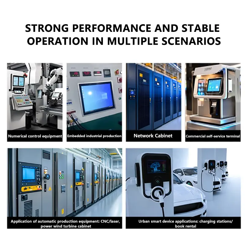
The module can be evaluated for:
- industrial instrument readouts;
- process-controller status windows;
- test and measurement tools;
- rack-mounted electronics;
- audio equipment;
- laboratory equipment;
- power-supply interfaces;
- communication equipment;
- embedded machine controls;
- smart appliance information strips;
- equipment alarm panels;
- compact operator interfaces.
Similar 5.5-inch green graphic OLED products are commonly positioned for industrial control, test and measurement, audio/video equipment and other status-oriented electronics, supporting this application direction without proving suitability for any specific regulated system.
Application approval should still cover operating environment, power design, update behavior, optical requirements and mechanical protection.
Customization and Variant Boundaries
Project review may include:
- green or optional yellow emission;
- interface-mode selection;
- FPC routing;
- ZIF orientation;
- pin-definition adaptation;
- cover lens;
- optical treatment;
- controller-board support;
- mechanical drawing changes;
- logo or packaging;
- mounting support.
Custom configurations are generally reviewed from 500 pieces, subject to tooling requirements, material availability and the requested specification. Sample and standard-module quantities are confirmed separately.
Touch is not confirmed as part of the standard panel. A touch requirement would require a separately engineered sensor, cover, controller and mechanical stack.
Procurement Checklist
Before approving the Bar Type PMOLED Display Module, confirm:
- Native 256 × 64 addressing
- Green or optional yellow emission
- Selected 3-wire SPI, 4-wire SPI or parallel mode
- Complete 30-pin assignment
- Connector pitch
- Connector contact side
- FPC thickness and orientation
- Voltage rails
- Current and power requirements
- Reset and initialization procedure
- Serial or parallel timing
- Interface-mode configuration
- Active area of 135.65 × 33.89 mm
- Module outline of 146 × 45 × 2 mm
- Visible window and black-mask dimensions
- FPC bend and connector-access space
- Cover-lens requirement
- Optical treatment
- Operating environment
- Required temperature range
- Sample validation
- Quantity and annual demand
- Production schedule
- Required compliance documentation
FAQ
About 5.5inch Bar Type PMOLED Display Module
What must be checked before selecting SPI or parallel control?
How should 256 × 64 content be organized for a narrow instrument window?
Does the 1/64 duty value define the host interface?
Is yellow emission included in the standard configuration?
What documents are required before enclosure and PCB release?
Freya Yang
+86 18318948097