Freya Yang
+86 18318948097
+852 62667476
13.3 Inch USB PCAP Display Module for Embedded Terminals
Model P/N
Size
Resolution
Brightness
Viewing Angle
Connector Type
Operating Temp
Overall(mm)
huisoar
HS133GG03BFD05AV1
Brand
Panel Size (inch)
Model P/N
Resolution
Brightness (nits)
Viewing Angle
Response Time
Overall (mm)
Active Area (mm)
Refresh Rate
Display Colors
Panel Type
Connector Type
Operating Temp
Touchscreen Type
Storage Temp
Work Mode
Pixel Format
Touch Interface
Control Type
Operating Environment
Designed For
13.3 Inch USB PCAP Display Module for Embedded Terminals
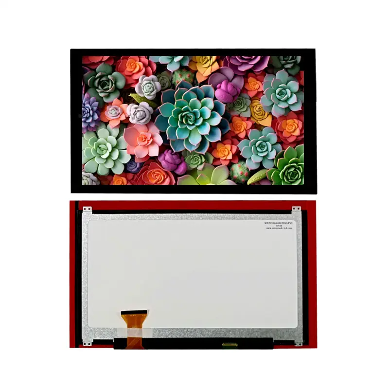
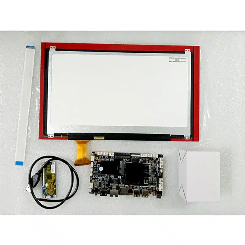
The 13.3 Inch USB PCAP Display Module combines a 1920 × 1080 TFT image area, eDP video transport and a USB capacitive-touch path for compact interactive equipment. Its Full HD format supports detailed menus, equipment graphics, status pages and touch-driven workflows without turning the assembly into a finished monitor.
The LCD image path, touch-control path, panel power, backlight and mechanical stack must be qualified separately. A matching connector or resolution does not establish complete compatibility.
Product Summary
This 13.3-inch touch assembly provides a 293.76 × 165.24 mm active area in a familiar 16:9 format. The transmissive, normally black TFT structure and full-viewing designation support interfaces that may be used from several normal operator positions.
The display information identifies eDP and USB as the system interfaces. In this configuration, eDP carries the LCD image path and USB carries the capacitive-touch control path.
The integrated construction is identified with an OCA touch-assembly remark. The complete cover lens, sensor outline, adhesive stack and cable arrangement should still be confirmed in the released mechanical drawing.
Key Specifications at a Glance
The module provides 1920 × 1080 pixels with an RGB vertical-stripe arrangement. Its active image area is 293.76 × 165.24 mm.
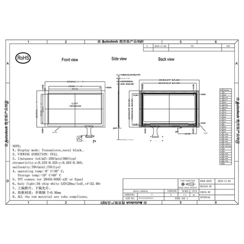
A listed combined envelope of 335.00 × 203.20 × 4.88 mm is provided, but the mechanical drawing contains separate LCD, CTP, cover and viewing-area boundaries. Production tooling should therefore follow the approved combined assembly drawing rather than a single marketplace dimension.
The panel luminance is 250 cd/m² minimum and 300 cd/m² typical. This level is intended primarily for indoor or controlled-light equipment.
Full HD Workspace for Embedded Interfaces
1920 × 1080 Image Area
Full HD resolution provides space for multi-zone operator pages, configuration dialogs, trend views, diagnostic content and fine status indicators. At 13.3 inches, the format offers more interactive area than smaller embedded screens while remaining practical for equipment consoles and countertop terminals.
The host must support the panel’s native timing and eDP link requirements. Resolution equality does not prove that another host, cable or controller board is compatible.
Normally Black Full-Viewing Operation
The TFT is specified as transmissive and normally black with a full-viewing designation. This supports interfaces that need consistent use from several normal positions around the equipment.
No numeric left, right, up or down angle sequence is assigned because the available information does not define directional values.
The completed optical stack should be assessed behind the intended cover lens. OCA bonding, surface finish, printed borders and installation lighting can affect perceived contrast and reflection behavior.
eDP Video and USB PCAP Integration
eDP Host Compatibility
A complete eDP compatibility review should cover:
- native 1920 × 1080 timing;
- eDP lane count and link rate;
- AUX-channel routing;
- panel power rails;
- enable and control signals;
- backlight power and control;
- full connector pin assignment;
- connector pitch and contact side;
- FPC orientation;
- cable length and routing.
A matching 30-pin connector does not guarantee eDP timing, lane or pin compatibility.
USB Touch-Control Qualification
The USB connection must be evaluated as a separate touch-control path. Engineering confirmation should include:
- touch-controller identity;
- USB device implementation;
- touch supply requirements;
- connector and pinout;
- touch-point count;
- coordinate mapping;
- host operating-system support;
- cover-lens thickness;
- grounding and cable routing.
A working eDP image does not prove that USB touch will enumerate or track correctly on the target host.
The eDP connection carries the LCD image path, while USB carries the capacitive-touch control path in this configuration.
ILI2511 Identification Boundary
ILI2511 is identified in the product information, but the name alone does not establish its exact role in the ordered assembly.
It does not prove:
- an LCD timing-controller function;
- host-side register programming;
- a required initialization sequence;
- supported touch-point count;
- USB operating-system compatibility;
- firmware requirements;
- power sequencing.
These details require the approved controller specification and complete interface documentation.
Mechanical Integration of the 13.3 Inch USB PCAP Display Module
Active Area and Combined Assembly Envelope
The active area measures 293.76 × 165.24 mm. The listed combined assembly envelope is 335.00 × 203.20 × 4.88 mm.
The enclosure design should account for:
- visible opening;
- LCD body;
- touch sensor;
- cover lens;
- adhesive or OCA stack;
- FPC exits;
- connector insertion space;
- cable bend radius;
- mounting tolerance;
- pressure-free glass support.
The 4.88 mm listed depth should not be used as the only enclosure-control dimension until the ordered assembly drawing is approved.
OCA Touch Stack and Drawing Control
OCA indicates an optically clear adhesive layer within the touch assembly. It does not by itself establish the complete bonding process, cover-glass thickness, surface treatment, optical performance or repair method.
The enclosure must be released against the approved combined LCD-and-touch drawing.
The drawing should distinguish:
- LCD active area;
- LCD outline;
- touch-sensor outline;
- cover-lens outline;
- visible opening;
- adhesive region;
- touch FPC;
- LCD FPC;
- connector orientation;
- tolerance stack.
Luminance and Environmental Boundaries
The luminance specification is 250 cd/m² minimum and 300 cd/m² typical. This supports many indoor terminals, equipment consoles and controlled-light interfaces.
It is not a sunlight-readable specification. The completed assembly should be tested under the target ambient light, especially when a cover lens, dark printing, additional coating or recessed mounting is used.
The operating-temperature range is 0°C to +50°C. Storage is specified from −10°C to +60°C.
These limits do not establish outdoor, automotive, freezer, high-humidity, condensation, vibration or medical qualification.
Recommended Application Routes
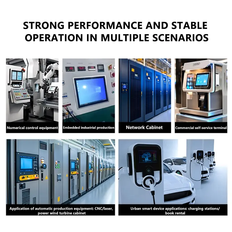
The module may be evaluated for:
- embedded terminals;
- compact operator consoles;
- smart equipment panels;
- indoor industrial interfaces;
- test and service equipment;
- equipment configuration terminals;
- interactive information interfaces.
These are integration routes rather than certification claims. Final approval depends on eDP compatibility, USB touch support, enclosure fit, optical performance, power design and environmental testing.
Customization and Sample Qualification
Project-specific review may cover:
- touch cover-lens dimensions;
- printed borders;
- OCA or alternative bonding construction;
- touch-controller and USB definition;
- LCD and touch FPC geometry;
- connector orientation;
- interface and pin definition;
- brightness target;
- packaging;
- mechanical adaptation;
- controller-board matching.
Custom production scope is confirmed according to the requested assembly. Standard-module samples and custom logo, packaging or graphic programs should be treated as separate commercial scopes.
A representative sample should be evaluated for:
- native image output;
- eDP link stability;
- USB enumeration;
- touch coordinate accuracy;
- edge-touch behavior;
- cable alignment;
- backlight performance;
- enclosure fit;
- optical appearance;
- temperature operation.
Procurement Checklist
Provide the following before sample or production approval:
- native 1920 × 1080 timing;
- host eDP lane count and link rate;
- complete host and panel pin assignments;
- panel and backlight power requirements;
- connector pitch and contact side;
- FPC orientation;
- touch-controller specification;
- USB touch requirements;
- required operating-system support;
- approved LCD-and-touch drawing;
- visible opening and enclosure depth;
- cover-lens construction;
- OCA or bonding requirement;
- target lighting conditions;
- operating and storage temperature requirements;
- sample quantity;
- annual demand;
- validation requirements;
- production schedule.
FAQ
About 13.3 Inch USB PCAP Display Module
What must be checked before connecting this module to an eDP host?
Does USB carry the image signal for this display assembly?
Which mechanical dimension should control the enclosure design?
What does the ILI2511 identification confirm?
Is 300 cd/m² typical sufficient behind the final cover lens?
Freya Yang
+86 18318948097