Freya Yang
+86 18318948097
+852 62667476
8 Inch 1280×800 Capacitive LVDS Display Module for HMI
Model P/N
Size
Resolution
Brightness
Viewing Angle
Connector Type
Operating Temp
Overall(mm)
huisoar
HS080WX22A-V1
Brand
Panel Size (inch)
Model P/N
Resolution
Brightness (nits)
Viewing Angle
Response Time
Overall (mm)
Active Area (mm)
Refresh Rate
Bezel Opening
Display Colors
Panel Type
Connector Type
Surface Treatment
Operating Temp
Touchscreen Type
Storage Temp
Work Mode
Pixel Format
Control Type
Weight (g)
Protective Glass Specification
Operating Environment
Motherboard Type
Designed For
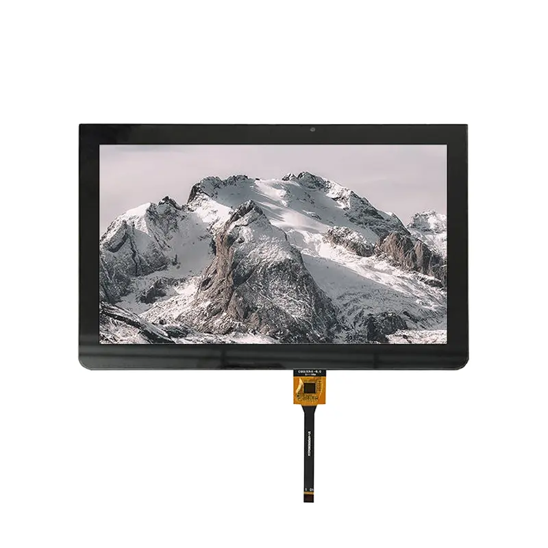
8 Inch 1280x800 Capacitive LVDS Display Module for HMI
A slim landscape TFT component with 350 cd/m² luminance, low-reflection surface treatment and capacitive-touch integration for embedded control equipment.
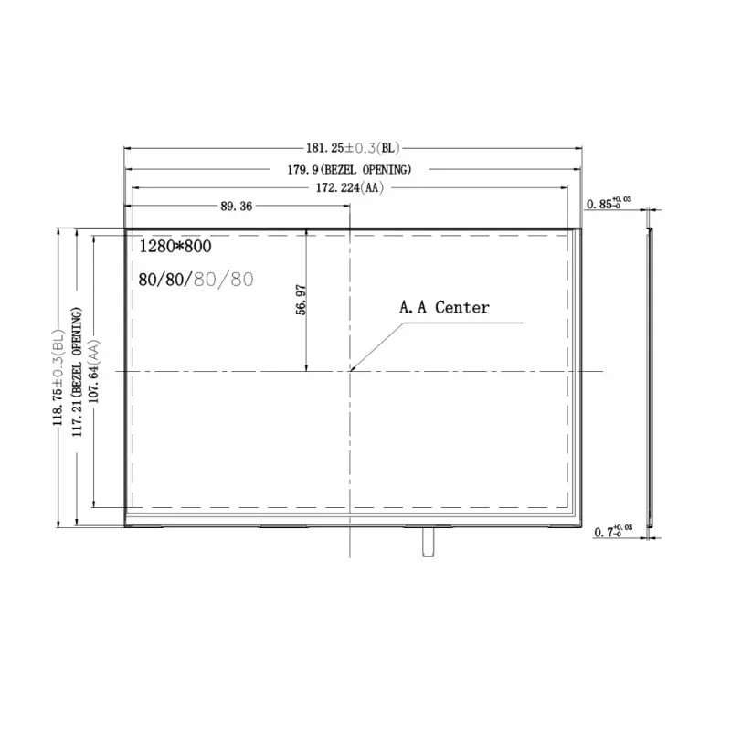
The 1280x800 Capacitive LVDS Display Module gives embedded product teams a landscape 8-inch interface for menus, machine status, diagnostic pages and touch-driven controls. Its 1280 × 800 pixel format provides more working space than lower-resolution compact panels, while the 172.222 × 107.64 mm active area fits within a 181.25 × 118.75 × 3.95 mm typical LCD outline.
The module uses an LVDS image interface, transmissive normally-black operation and a capacitive-touch product configuration. The touch controller and touch communication interface must be confirmed for each project rather than inferred from the touch type.
Key Specifications at a Glance
| Parameter | Confirmed value |
|---|---|
| Display size | 8 inch |
| Resolution | 1280 × 800 pixels |
| Orientation | Landscape |
| Active area | 172.222 × 107.64 mm |
| LCD outline | 181.25 × 118.75 × 3.95 mm typical |
| Pixel pitch | 0.13455 × 0.13455 mm |
| Pixel arrangement | RGB stripe |
| Display mode | Transmissive, normally black |
| Display colors | 16.7 million, 8-bit + Hi-FRC listed |
| Luminance | 350 cd/m² |
| Viewing specification | 80/80/80/80° listed |
| Display interface | LVDS |
| Touch configuration | Capacitive touch |
| Surface treatment | Hard coating, 3H |
| Front polarizer | Low reflection |
| LCD weight | 107 g maximum |
| Backlight | Bottom-edge lighting bar with 36-LED array |
Final production release should follow the approved electrical specification, LCD drawing, touch drawing and qualified sample.
1280×800 Landscape UI Performance
The 1280 × 800 format provides a 16:10 landscape workspace for embedded interfaces that need more horizontal room than portrait modules.
Suitable interface layouts
The available display area can support:
- Machine overview pages
- Process diagrams
- Split-screen status panels
- Trend charts
- Alarm histories
- Diagnostic menus
- Parameter-entry forms
- Equipment illustrations
- Camera or image previews
- Touch-based navigation bars
The native resolution should be used wherever practical. Scaling a lower-resolution interface can soften text and icons, while excessive UI density can make touch controls physically difficult to operate.
Physical touch-target planning
The 172.222 × 107.64 mm active area should be considered together with viewing distance and operator conditions. A high pixel count does not automatically make very small buttons practical.
Button dimensions, fonts and spacing should be tested on the physical sample, especially for equipment used while standing, moving or wearing work gloves. Glove support itself is not assumed and requires touch-system qualification.
Optical Performance for Controlled-Light Equipment
The module is specified at 350 cd/m² and uses a transmissive normally-black TFT structure.
350 cd/m² use boundary
The 350 cd/m² configuration is primarily suited to indoor or controlled-light equipment. It can support readable menus, numerical information, status graphics and ordinary HMI content when reflections are managed appropriately.
The 350 cd/m² rating does not establish direct-sunlight readability.
A touch sensor, cover glass, printed border or protective overlay can reduce delivered luminance and add reflections. Optical approval should therefore be completed with the final front stack rather than with an uncovered LCD alone.
Viewing specification
A raw 80/80/80/80° viewing sequence is listed. Because its directional order is not explicitly defined, the values are not assigned to up, down, left or right in the public description.
Sample evaluation should include:
- Straight-on viewing
- Off-axis landscape viewing
- Installed mounting angle
- Dark-screen behavior
- Color shift
- Luminance uniformity
- Touch-cover reflection
Low-Reflection 3H Surface Design
The LCD specification identifies hard coating with a 3H rating and a low-reflection front polarizer.
Surface-treatment value
The surface treatment can help reduce ordinary handling marks and moderate reflections compared with an untreated front polarizer. It should not be described as impact proof, vandal resistant or equivalent to a hardened external cover lens.
When the capacitive-touch assembly is fitted, the final visible surface may be the touch cover rather than the LCD polarizer. The touch-cover material, hardness, coating and optical transmission must therefore be reviewed separately.
Final-stack optical assessment
For a finished HMI, check:
- Cover-glass transmission
- Printed-border width
- Air gap or bonding method
- Surface reflection
- Fingerprint visibility
- Touch sensitivity
- Mechanical stress
- Bezel shadow
- Available luminance at the user surface
LVDS Host and Controller Qualification
LVDS describes the display signal family, but it does not guarantee that two LVDS panels can use the same host, cable or connector.
An LVDS label does not establish connector or timing compatibility.
Required host checks
Before connecting the panel, verify:
- Native 1280×800 timing
- Pixel-clock range
- Horizontal and vertical timing
- LVDS channel count
- JEIDA or VESA mapping where applicable
- Color mapping and bit width
- Complete connector pinout
- Panel supply voltage
- Logic requirements
- Enable and control signals
- FPC or cable orientation
- Pin-1 position
- Backlight power path
An unmatched pinout or supply can prevent operation or damage the module.
Non-LVDS host platforms
MIPI DSI, eDP, HDMI, parallel RGB and USB video outputs cannot be treated as direct substitutes for LVDS.
A controller or bridge may be required when the processor does not provide the panel’s native LVDS timing and signal mapping. Controller selection must use the complete electrical specification rather than resolution and connector shape alone.
1280x800 Capacitive LVDS Display Module Touch Integration
The product configuration includes capacitive touch, but the LCD image path and the touch-input path should be treated as separate subsystems.
Capacitive touch does not prove USB, I²C, SPI or another specific interface.
Touch information required before PCB release
Confirm:
- Touch-controller part number
- Touch communication interface
- Touch supply voltage
- Logic voltage
- Connector and pin assignment
- Reset and interrupt signals
- Touch-point count
- Coordinate orientation
- Firmware or driver requirements
- Cover-glass structure
- Touch FPC orientation
- Complete touch-module dimensions
The LCD can be electrically compatible while the touch path remains incompatible, so both interfaces require separate approval.
Coordinate and orientation validation
The touch coordinate system should be checked against the 1280 × 800 landscape image orientation. Rotation, axis inversion and display-to-touch alignment should be tested on the intended operating system and host platform.
No operating-system compatibility is claimed without a confirmed touch controller and software path.
Mechanical Fit and Enclosure Planning
The LCD active area is 172.222 × 107.64 mm, while the typical panel outline is 181.25 × 118.75 × 3.95 mm.
Active area, bezel and outline
The active image area is smaller than both the bezel opening and the outer panel dimensions. Housing design should distinguish:
- Active image area
- Visible opening
- LCD outer outline
- Touch sensor outline
- Touch cover outline
- Total stack thickness
- FPC exit zone
- Connector-clearance zone
The drawing indicates a bezel opening of approximately 179.9 × 112.21 mm, but this value should be checked against the approved drawing revision before tooling.
FPC and rear-component clearance
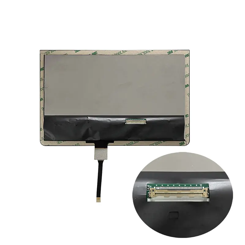
The module includes a bottom FPC region. Enclosure design should provide clearance for:
- FPC exit
- Minimum bend radius
- Connector engagement
- Rear components
- Adhesive or mounting tape
- Touch-controller components
- Cable strain relief
- Assembly access
The 3.95 mm typical LCD thickness should not be used as the complete touch-product thickness unless the touch drawing confirms it.
Backlight Structure and Driver Review
The module uses a bottom-edge lighting structure with a 36-LED array.
Backlight terminology
The confirmed information establishes LED count and edge position, but it does not establish the required voltage, current, dimming method, thermal limit or lifetime grade.
A backlight driver should be selected only after confirming:
- LED series/parallel topology
- Forward-voltage range
- Current requirement
- Enable logic
- Dimming input
- Startup behavior
- Maximum power
- Thermal design
- Required luminance range
A 36-LED count alone does not define the correct driver.
Thermal and optical validation
Backlight performance should be evaluated inside the finished enclosure. Heat buildup, airflow, cover transmission and dimming strategy can affect luminance uniformity and long-term behavior.
No backlight-lifetime claim is made because a verified lifetime grade and reference conditions are not available.
Recommended Application Routes
The module can be evaluated for:
- Embedded HMI terminals
- Industrial tablets
- Machine-side operator panels
- Smart equipment interfaces
- Diagnostic tools
- Portable test and service equipment
- Building-control terminals
- Compact POS operator interfaces
- Indoor information terminals
- Tablet-style control devices
Application approval must consider lighting, temperature, touch behavior, enclosure design, signal compatibility and regulatory requirements.
It should not be promoted as an automotive, medical, outdoor, waterproof or payment-certified component without application-specific qualification.
Customization and Engineering Review
Project review may cover:
- LCD and touch FPC layout
- LVDS pin definition
- Touch-controller selection
- Touch communication route
- Cover-glass outline
- Printed border
- Surface treatment
- Optical bonding assessment
- Brightness target
- Backlight driver
- Mechanical stack
- Connector matching
- Controller or bridge board
- Packaging and branding
Custom configurations are generally reviewed from 1,000 pieces, subject to tooling requirements, material availability and the requested specification. Samples and standard-module quantities are confirmed separately.
Procurement Checklist
Before approving a sample or controller PCB, confirm:
- Native 1280×800 timing
- LVDS channel count
- LVDS signal mapping
- Color depth and mapping
- Complete LCD connector pinout
- Connector pitch and mating part
- Panel supply voltage
- Logic and control voltages
- FPC contact side
- Pin-1 orientation
- Backlight voltage range
- Backlight current requirement
- Dimming and enable method
- Touch-controller part number
- Touch communication interface
- Touch connector pinout
- Touch supply and I/O voltage
- Reset and interrupt routing
- Required touch-point count
- Host-driver support
- Display and touch coordinate orientation
- Active area: 172.222 × 107.64 mm
- LCD outline: 181.25 × 118.75 × 3.95 mm typical
- Bezel opening
- Complete touch outline
- Total touch-stack thickness
- FPC bend and connector clearance
- 350 cd/m² ambient-light fit
- Surface reflection
- Operating-temperature requirement
- Sample quantity
- Annual demand
- Controller-board requirement
- Production schedule
FAQ
About 1280x800 Capacitive LVDS Display Module
What must be checked before replacing another 8-inch 1280×800 LVDS panel?
Is 350 cd/m² sufficient behind a capacitive-touch cover?
Which dimensions should control the enclosure opening?
Can the capacitive touch connect directly to USB or I²C?
When is an LVDS controller or bridge board required?
Freya Yang
+86 18318948097