Freya Yang
+86 18318948097
+852 62667476
7 Inch LVDS Touch Display Module for Smart Terminals
Model P/N
Size
Resolution
Brightness
Viewing Angle
Connector Type
Operating Temp
Overall(mm)
huisoar
HS070UG56A-V1
Brand
Panel Size (inch)
Model P/N
Resolution
Brightness (nits)
Viewing Angle
Response Time
Overall (mm)
Active Area (mm)
Refresh Rate
Display Colors
Panel Type
Connector Type
Surface Treatment
Operating Temp
Touchscreen Type
Storage Temp
Work Mode
Pixel Format
Control Type
Weight (g)
Operating Environment
Motherboard Type
Designed For
7 Inch LVDS Touch Display Module for Smart Terminals
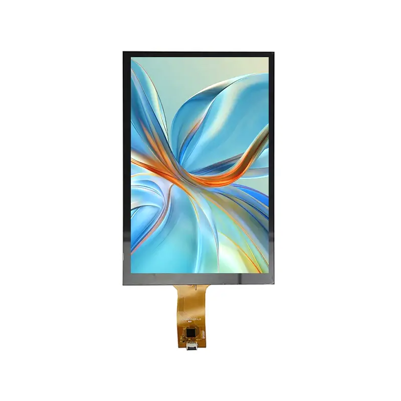
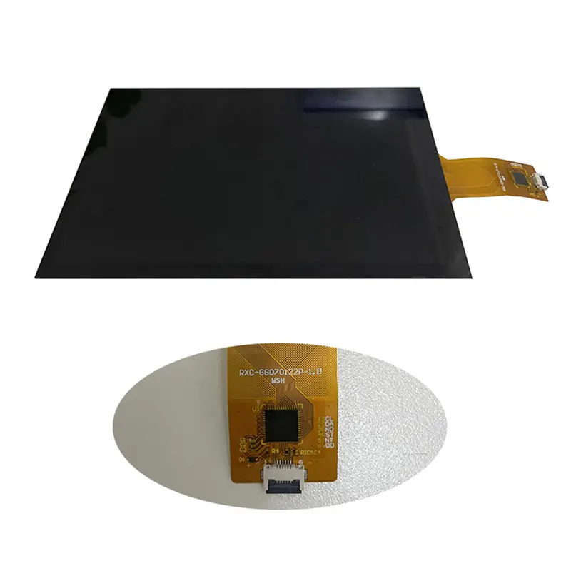
This high-density portrait TFT combines a 1200×1920 LVDS image path with separate I²C touch control for compact embedded interfaces.
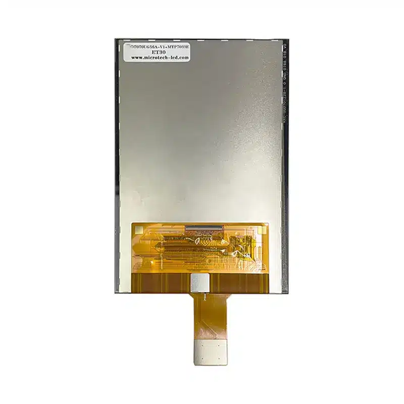
The 7 Inch LVDS Touch Display Module is a portrait-format component for smart terminals and embedded systems that require a narrow screen with dense visual content. Its 1200×1920 resolution provides significantly more vertical workspace than conventional 800×480 or 1024×600 industrial panels, while the LVDS display connection and separate I²C touch path support integration into custom controller hardware.
The module is intended for product designs where display timing, touch routing, enclosure geometry, and production drawings can be qualified before PCB and mechanical release.
Key Specifications at a Glance
| Parameter | Value |
|---|---|
| Display size | 7.0 inch |
| Resolution | 1200 × 1920 pixels |
| Orientation | Portrait |
| Display interface | 40-pin LVDS |
| Touch-control interface | I²C |
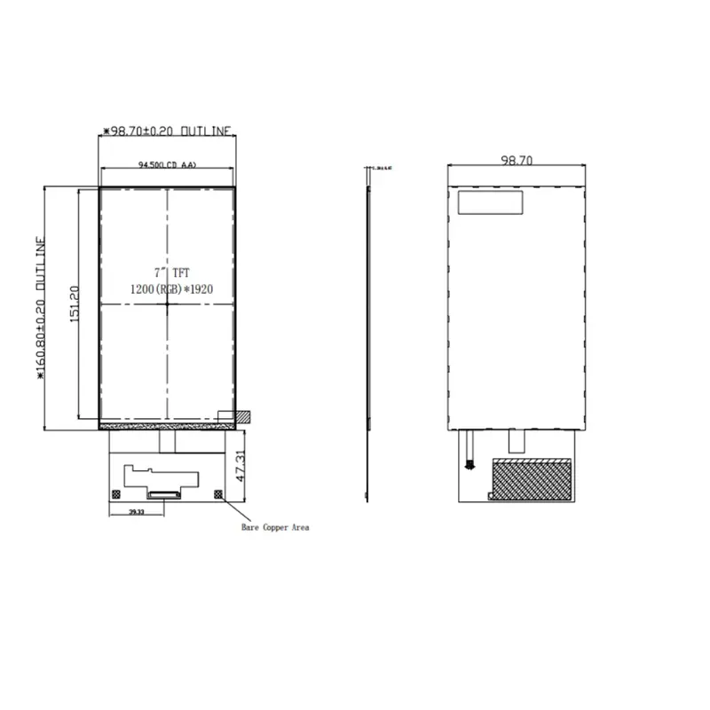
| Active area | 94.5 × 151.2 mm |
| Panel outline | 97.3 ± 0.2 × 159.4 ± 0.2 × 0.68 ± 0.08 mm, without FPC |
| Luminance | 400 cd/m² |
| Viewing angle | 80/80/80/80° |
| Color gamut | 80% typical |
| Operating temperature | −20°C to +70°C |
| Storage temperature | −30°C to +80°C |
A production design must be validated against the approved LVDS timing, full 40-pin assignment, touch circuit, voltage domains, backlight specification, FPC orientation, and final mechanical drawing.
1200×1920 Portrait UI Performance
The native 1200×1920 format creates a tall interface for menus, lists, process information, image previews, parameter pages, and app-style navigation. It is suited to devices that need more vertical content than a landscape screen can provide within the same diagonal size.
High-density interface layout
The 94.5 × 151.2 mm active area allows designers to place detailed text, icons, charts, and touch targets in a relatively compact front panel. UI assets should be developed for the native resolution wherever possible to avoid scaling artifacts and unnecessary processing.
The portrait format can support:
- Stacked parameter controls
- Long device-status lists
- Vertical navigation menus
- Image-rich setup screens
- Access and identification workflows
- Scrollable control interfaces
RGB vertical-stripe structure
The panel uses an RGB vertical-stripe arrangement. Its listed pixel pitch is 78.75 × 78.75 µm, while the subpixel dot pitch is 26.25 × 78.75 µm.
These dimensions should be used when evaluating text sharpness, icon design, and optical inspection criteria.
40-Pin LVDS Host Compatibility
The display uses a 40-pin LVDS connection, but the physical pin count does not define the electrical mapping.
Parameters that must match
Before releasing the host board, confirm:
- Native 1200×1920 timing
- LVDS channel configuration
- Clock polarity
- Data mapping
- Color-depth operating mode
- Pixel-clock range
- Supply and logic-voltage domains
- Reset and enable behavior
- Backlight enable and dimming signals
- Complete 40-pin assignment
- Connector pitch and mating part
- FPC contact side and insertion orientation
A controller that drives another 40-pin LVDS panel may still be incompatible with this module.
Interface-conversion requirements
HDMI, DisplayPort, eDP, MIPI DSI, RGB, and USB video cannot connect directly to a native LVDS image input. A suitable bridge or controller board is required when the host does not provide the approved LVDS signal.
The controller must support the full 1200×1920 portrait timing rather than merely accepting the same nominal resolution.
Separate I²C Touch-Control Path
The touch-control interface is identified as I²C. It should be treated separately from the LVDS image path.
Display and touch are independent interfaces
The LVDS connection transports display data. The touchscreen requires its own control connection, normally including:
- I²C clock
- I²C data
- Interrupt
- Reset
- Supply
- Ground
A host must therefore provide both compatible LVDS display output and the GPIO/I²C resources required by the touch circuit.
This separation is common in LVDS touch-display integration; published embedded-board guidance similarly routes the LCD and capacitive-touch controller through distinct connections.
Touch-controller qualification
FT7250 appears as a compatible touch-controller reference. That reference does not establish that every production unit uses the same IC, firmware, address, touch-point count, or voltage domain.
The approved touch schematic should confirm:
- Final controller part number
- I²C address
- Reset timing
- Interrupt polarity
- Logic voltage
- Coordinate orientation
- Firmware or operating-system support
- Cover-lens calibration
Optical Performance for Controlled-Light Equipment
The module is specified at 400 cd/m² with an 80% typical color gamut.
Luminance boundary
The 400 cd/m² configuration is intended primarily for indoor or controlled-light equipment. It should not be described as direct-sunlight readable without completed optical testing.
Finished brightness can be affected by:
- Touch glass
- Cover-lens printing
- Adhesive
- Air gaps
- Protective windows
- Surface reflections
- Enclosure shadowing
- Viewing orientation
Normally black transmissive mode
The panel uses normally black, transmissive operation. This supports dark-background interfaces and image-rich applications, but the final contrast result depends on the approved backlight, polarizers, cover construction, and ambient lighting.
Viewing-angle sequence
The documented viewing sequence is 80/80/80/80°, with the accompanying note identifying equal U/D/L/R performance. This supports installations where users may approach the terminal from different directions.
Mechanical Integration of the 7 Inch LVDS Touch Display Module
The primary bare-panel outline is 97.3 ± 0.2 × 159.4 ± 0.2 × 0.68 ± 0.08 mm without the FPC.
Slim bare-panel construction
The low listed panel thickness supports compact product designs, but it does not represent the complete touch assembly, cover lens, adhesive, support frame, connector clearance, or rear-component envelope.
The enclosure design should provide:
- Controlled support around non-active regions
- No pressure on the display area
- FPC bend clearance
- Connector insertion space
- Rear-component clearance
- Protection against panel twist
- Touch-cover and adhesive tolerances
- Service access for sample replacement
Drawing conflict requires approval
An alternate FT7250-related drawing gives approximately 98.7 × 160.8 × 2.2 mm. That difference may represent another IC, COG, touch, or assembly configuration.
The mechanical design must use the final drawing assigned to the approved production part rather than combining values from different configurations.
Panel mounting
The product information identifies panel mounting. The mounting method should be finalized with the bezel, support points, cover construction, and touch-stack drawing to avoid stress on the thin TFT glass.
Color-Depth and Driver-IC Qualification
The technical material includes more than one color-depth and IC reference.
Color-depth discrepancy
One table states 1.07B colors with an 8+2-bit notation, while another table gives 16.7M. These values should not be combined into one marketing claim.
The host and module specification should confirm:
- Effective LVDS color depth
- Dithering or FRC operation
- LVDS mapping
- Controller output mode
- Accepted test pattern
- Production inspection criteria
IC references
H/25U appears as a D-IC reference, while another table lists 3×ST5821C + 1×ST5084C. The exact role and final production combination cannot be inferred from those names alone.
The approved module specification should identify the production IC configuration and its datasheet-defined electrical, timing, and power requirements.
Temperature Range and Use Environment
The stated operating range is −20°C to +70°C, with storage from −30°C to +80°C.
These limits define the panel-level temperature window but do not establish:
- Outdoor qualification
- Condensation resistance
- Waterproofing
- UV resistance
- Vibration grade
- Automotive qualification
- Medical certification
- Finished-product reliability
System testing should include the host board, touch stack, enclosure, adhesives, backlight, and thermal design.
Recommended Applications
The module can be evaluated for:
- Smart terminals
- Portrait embedded HMI
- Building-control interfaces
- Access-control terminals
- Compact operator panels
- Image-rich industrial controls
- Portable test and service equipment
- Equipment setup terminals
- Connected appliance interfaces
- Vertical information panels
Regulated, outdoor, safety-critical, or transportation applications require separate system-level qualification.
Customization and Project Review
Project review may cover:
- LCD and touch configuration
- Final touch-controller choice
- Cover-lens structure
- FPC shape and exit location
- Pin definition
- LVDS mapping and timing
- Brightness target
- Mechanical outline
- Mounting support
- Surface treatment
- Controller or bridge-board matching
- Packaging and documentation
Custom configurations are reviewed case by case, subject to tooling, material availability, engineering feasibility, and requested specification. Samples and standard-module quantities are confirmed separately.
Procurement and Sample Approval Checklist
Confirm the following before releasing the controller PCB and enclosure:
- Native 1200×1920 timing
- LVDS channel and mapping configuration
- Pixel-clock requirements
- Final color-depth mode
- Complete 40-pin pinout
- Connector pitch and mating part
- FPC contact side and orientation
- LCD power and logic-voltage domains
- Backlight electrical requirements
- Touch-controller part number
- I²C address
- Reset and interrupt routing
- Touch logic voltage
- Coordinate orientation
- 94.5 × 151.2 mm active area
- Approved overall drawing
- Panel versus touch-assembly thickness
- Mounting and support locations
- 400 cd/m² lighting suitability
- Operating and storage temperatures
- Sample quantity
- Annual demand
- Controller-board requirement
- Production schedule
FAQ
About 7 Inch LVDS Touch Display Module
What must be checked before replacing another 40-pin LVDS panel?
How should the LVDS display and I²C touchscreen be connected?
Which mechanical dimensions should be used for enclosure design?
How should the mixed 1.07B and 16.7M color references be handled?
When is an LVDS bridge or controller board required?
Freya Yang
+86 18318948097