Freya Yang
+86 18318948097
+852 62667476
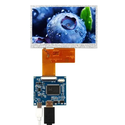
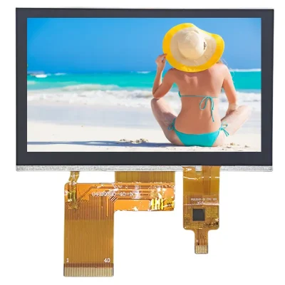
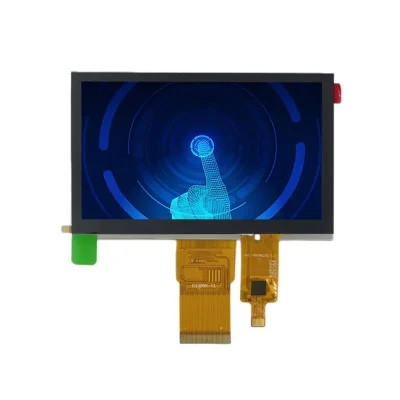
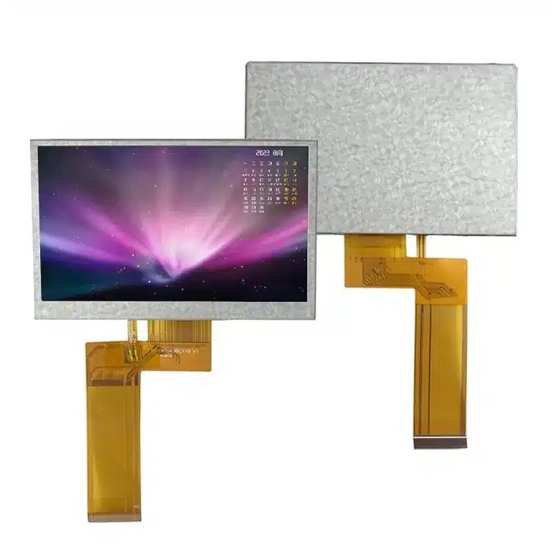
4.3 Inch Smart Home RGB TFT Display Module for Control Panels
Model P/N
Size
Resolution
Brightness
Viewing Angle
Connector Type
Operating Temp
Overall(mm)
huisoar
HS043BC018-04
Brand
Panel Size (inch)
Model P/N
Resolution
Brightness (nits)
Viewing Angle
Contrast Ratio
Response Time
Overall (mm)
Active Area (mm)
Refresh Rate
Bezel Opening
Display Colors
Panel Type
Connector Type
Operating Temp
Touchscreen Type
Storage Temp
Work Mode
Pixel Format
Operating Environment
Designed For
4.3 Inch Smart Home RGB TFT Display Module for Control Panels
This 4.3-inch IPS module pairs a 24-bit parallel RGB interface with 450 cd/m² typical luminance and a slim 3.1 mm profile for embedded control panels.
Product Summary
The Smart Home RGB TFT Display Module is a 480 × 272 component display for wall-mounted controllers, appliance interfaces, and compact embedded panels. Its IPS normally black architecture, 1000:1 typical contrast ratio, and listed 85°/85°/85°/85° viewing-angle sequence support interfaces that may be observed from more than one position.
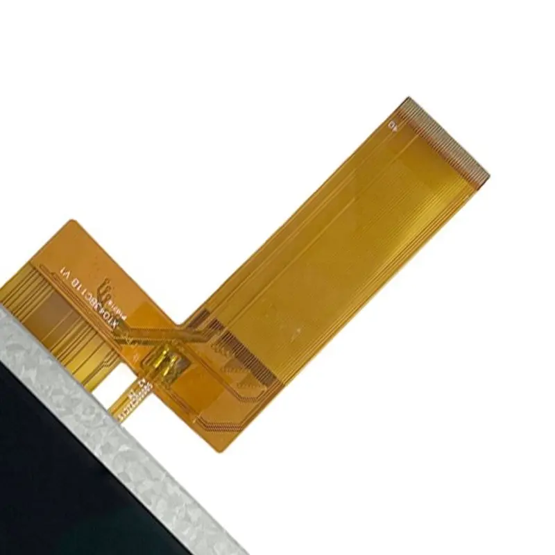
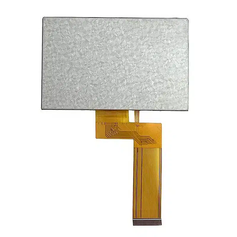
The standard configuration uses a 40-pin FPC and 24-bit parallel RGB. Capacitive or resistive touch can be evaluated as a separate option. A matching 40-pin connector does not prove pinout, voltage, timing, data mapping, or FPC-orientation compatibility.
Key Specifications at a Glance
| Parameter | Confirmed value |
|---|---|
| Display size | 4.3 inches |
| Resolution | 480 × 272 pixels |
| Panel mode | IPS, normally black |
| Luminance | 450 cd/m² typical |
| Contrast ratio | 1000:1 typical |
| Viewing angle | 85°/85°/85°/85° typical listed sequence |
| Response time | 40 ms typical, Tr + Tf |
| Dot pitch | 0.198 × 0.198 mm |
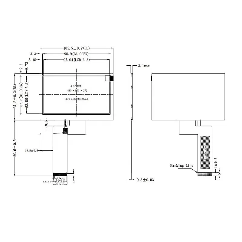
| Active area | 95.04 × 53.86 mm |
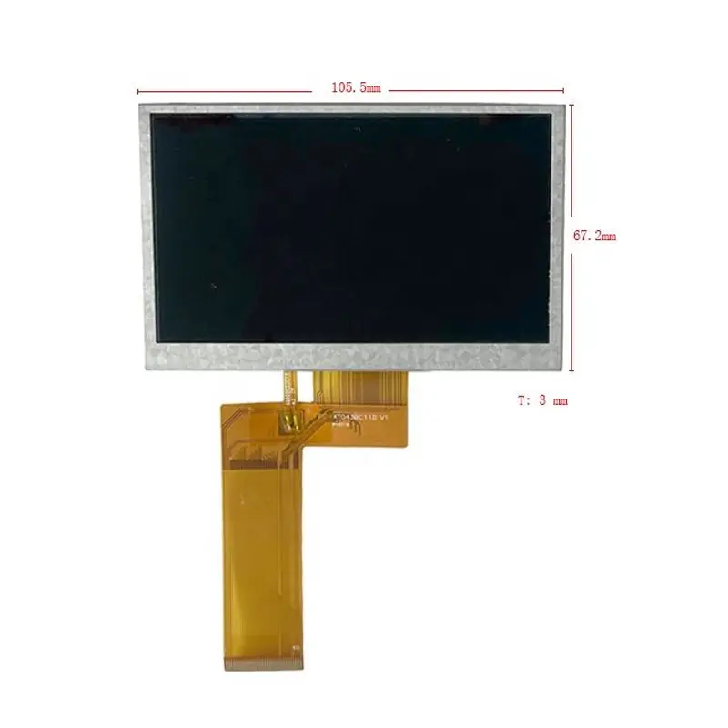
| Module outline | 105.5 × 67.2 × 3.1 mm |
| Backlight | 10-chip WLED, 5S2P, 16 V / 40 mA |
| Backlight life | 35,000 hours minimum |
| Display interface | 24-bit parallel RGB |
| LCD connection | 40-pin FPC |
| Driver IC | ST7283 |
| Touch | Optional CTP or RTP |
| Operating temperature | −20°C to +70°C |
| Storage temperature | −30°C to +80°C |
480 × 272 Interface Planning
Use the Native WQVGA Raster
Prepare menus, status graphics, icons, and touch targets at the native 480 × 272 raster. Confirm the scan direction, RGB order, clock polarity, data-enable or synchronization mode, porch values, and refresh timing before software release. Resolution alone does not define the complete host timing.
Match Information Density to the Viewing Distance
The 0.198 × 0.198 mm dot pitch is suitable for concise menus, operating status, numeric values, and short prompts. Verify the smallest text and icons through the intended cover lens and at the expected viewing distance.
Smart Home RGB TFT Display Module Integration
Qualify the 40-Pin Parallel RGB Connection
The module uses a 40-pin FPC for 24-bit parallel RGB data and related control signals. Review the complete pin assignment, FPC pitch, contact side, insertion direction, panel voltage, data mapping, pixel clock, synchronization, reset, and ground distribution.
An HDMI, MIPI DSI, eDP, LVDS, USB, or serial host requires a suitable controller or bridge that generates the approved parallel RGB timing. A connector adapter alone does not convert the video protocol. Parallel RGB architectures use dedicated color-data and timing/control lines rather than a low-pin-count serial image path.
Keep the Backlight Power Domain Separate
The listed WLED backlight uses a 10-chip 5S2P arrangement with a 16 V / 40 mA electrical reference. Confirm driver tolerance, enable logic, dimming method, startup behavior, cable loss, and thermal limits.
Do not apply the backlight voltage to the panel-logic pins. The panel-logic input voltage must be confirmed before schematic release.
Treat ST7283 as an Identification Reference
ST7283 identifies the TFT driver IC used in the module. It does not establish universal initialization, timing, gamma, reset, or power-sequence compatibility. Use the approved documentation for the exact production revision.
450 cd/m² Optical Performance
Validate the Finished Front-of-Screen Result
For the Smart Home RGB TFT Display Module, 450 cd/m² typical luminance supports many indoor control-panel and moderately bright equipment environments. It does not establish direct-sunlight readability.
A cover lens, optional touch panel, adhesive, printed border, fingerprints, and ambient reflections can reduce perceived brightness and contrast. Evaluate the complete optical stack under the actual installation lighting.
Preserve the Parameter Grades
The 1000:1 contrast ratio is specified as typical. The viewing-angle data is listed as 85°/85°/85°/85° typical, but its directional order is not defined. Keep the original sequence until an approved datasheet assigns left, right, up, and down.
The 40 ms response value is a typical Tr + Tf total. It should not be described as a fast-motion grade without application testing.
Mechanical Integration
Separate Active Area, Opening, and Outline
The 95.04 × 53.86 mm active area controls the visible image. The drawing also identifies a 98.9 × 57.7 mm backlight opening, while the 105.5 × 67.2 × 3.1 mm outline controls the enclosure cavity.
Add tolerances, cable routing, FPC bend radius, connector access, support surfaces, and any optional touch or cover-lens extension before releasing tooling.
Avoid Panel Stress
Mount the module on controlled support points without twisting the frame or pressing on the active area. Verify the black mask, bezel opening, adhesive stack, and FPC movement after assembly.
Optional Touch Configuration
Capacitive touch and resistive touch are optional configurations rather than standard features of every unit. CTP may suit finger-operated smart-home panels, while RTP may be considered when stylus input or pressure activation is required.
The touch controller, interface, touch-point count, cover-lens construction, transparency, hardness, and assembled thickness require configuration-specific documentation.
Application and Environmental Boundaries
The Smart Home RGB TFT Display Module can be evaluated for wall-mounted smart-home controllers, appliance interfaces, lighting or HVAC panels, compact industrial controls, access interfaces, and embedded status terminals.
The −20°C to +70°C operating range and −30°C to +80°C storage range define temperature boundaries only. They do not establish waterproofing, condensation resistance, vibration grade, ultraviolet durability, medical certification, automotive qualification, or outdoor-system suitability.
Customization and Procurement
FPC shape and pin definition, backlight brightness, CTP or RTP integration, cover-lens design, printed border, surface treatment, optical bonding, enclosure fit, branding, and packaging may be reviewed by project.
Custom configurations are generally reviewed from 500 pieces, subject to tooling requirements, material availability, and the requested specification. Sample and standard-module quantities are confirmed separately.
Procurement Checklist
Confirm before sample approval:
- Assigned model HS043BC018-04 and supplier model ZH043BC018-04.
- Native 480 × 272 timing, RGB order, clock polarity, synchronization or DE mode, and refresh target.
- Complete 40-pin FPC assignment, pitch, contact side, insertion direction, and mating connector.
- Panel-logic voltage, current, reset, and power-sequence requirements.
- ST7283 command, timing, and gamma documentation.
- WLED driver design for the 16 V / 40 mA, 10-chip 5S2P reference.
- 95.04 × 53.86 mm active area, 98.9 × 57.7 mm opening, and 105.5 × 67.2 × 3.1 mm module fit.
- Standard no-touch configuration or the selected CTP/RTP drawing, controller, and interface.
- 450 cd/m² optical target behind the final cover stack.
- Operating environment, sample criteria, quantity, and annual demand.

FAQ
About 4.3 Inch Smart Home RGB TFT Display Module
What must be checked before connecting a 40-pin RGB controller?
Can a microcontroller drive the display directly?
Is 450 cd/m² sufficient behind a smart-home cover lens?
When should CTP or RTP be selected?
Which dimensions should control enclosure release?
Freya Yang
+86 18318948097