Freya Yang
+86 18318948097
+852 62667476
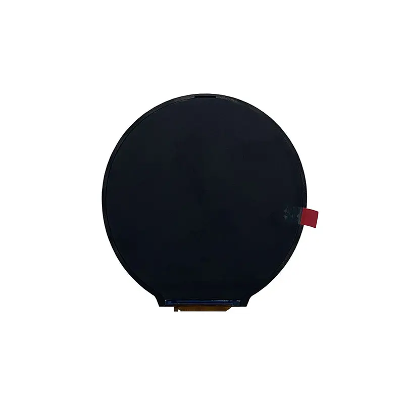
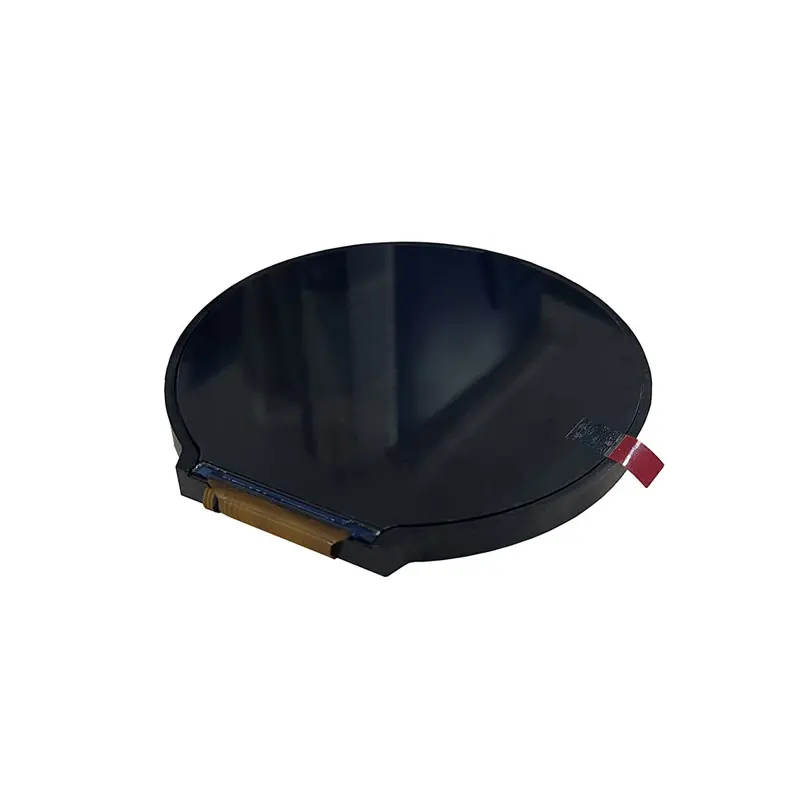
4 Inch High Brightness MIPI Round TFT Panel for Industrial Dials
Model P/N
Size
Resolution
Brightness
Viewing Angle
Connector Type
Operating Temp
Overall(mm)
huisoar
HS040HD22A-V1
Brand
Panel Size (inch)
Model P/N
Resolution
Brightness (nits)
Viewing Angle
Contrast Ratio
Response Time
Overall (mm)
Active Area (mm)
Refresh Rate
Display Colors
Panel Type
Connector Type
Operating Temp
Touchscreen Type
Storage Temp
Work Mode
Pixel Format
Input Voltage (V)
Operating Environment
Designed For
4 Inch High Brightness MIPI Round TFT Panel for Industrial Dials
A 720 × 720 IPS display with a three-data-lane MIPI connection, 800 cd/m² minimum luminance and a 39-pin FPC for circular control interfaces.
Product Summary
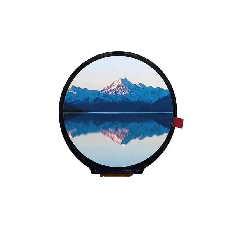
The High Brightness MIPI Round TFT Panel is a 4-inch IPS component for industrial dials, smart-appliance controls and compact circular HMIs. Its native 720 × 720 raster supports gauges, status rings, menus and centered data layouts without converting content from a rectangular aspect ratio.
The panel uses normally black transmissive mode, 16.7 million colors, 60% NTSC typical gamut and a listed 1200:1 contrast ratio. All-o’clock viewing supports installations approached from different positions. The standard drawing represents a display-only assembly; touch requires a separately approved configuration.
Key Specifications
| Parameter | Confirmed value |
|---|---|
| Display size | 4.0 inches |
| Resolution | 720 × 720 pixels |
| Panel type | IPS TFT, normally black, transmissive |
| Display colors | 16.7 million |
| Color gamut | 60% NTSC typical |
| Contrast ratio | 1200:1 |
| Luminance | 800 cd/m² minimum |
| Viewing direction | All O’Clock |
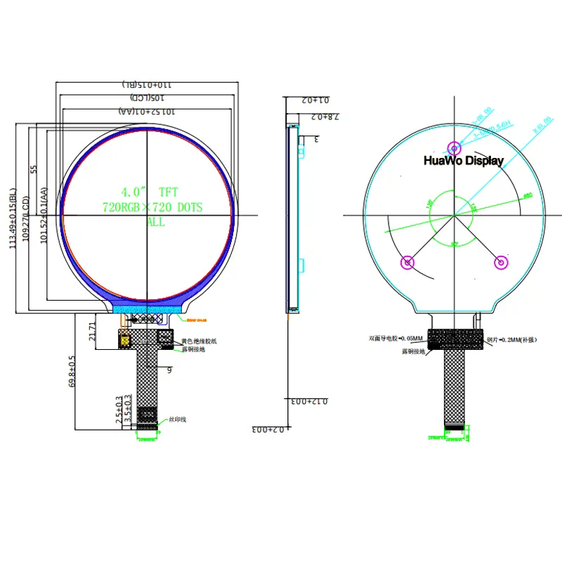
| Active area | 101.52 × 101.52 mm |
| Module outline | 110.00 × 113.49 × 7.80 mm |
| Listed subpixel pitch | 0.047 × 0.141 mm |
| Pixel arrangement | RGB stripe |
| Interface | Three-data-lane MIPI with clock lane |
| Connector | 39-pin FPC |
| Driver IC | FL7707N |
| I/O supply | 1.8 V |
| LCD bias rails | +6.3 V / −6.3 V |
| Backlight | 20 white LEDs, 5S4P |
| Backlight current | 180 mA |
| Operating temperature | −30°C to +80°C |
| Storage temperature | −30°C to +80°C |
| Touch | Not included in the standard drawing |
720 × 720 Circular UI Planning
Use the Native Square Raster
A round visible area still uses a square 720 × 720 pixel matrix. Generate native-resolution content so gauges, icons and text remain sharp. Place primary information inside a circular safe zone and reserve margin for the bezel, printed mask and cover-lens tolerance.
Review Multiple Viewing Positions
All-o’clock wording is useful for equipment gauges and wall-mounted dials. It does not define a numerical direction sequence, so left, right, up and down angles should not be assigned without an approved optical specification.
Evaluate the display through the selected cover material and mounting angle because these layers affect reflections, perceived contrast and edge visibility.
High Brightness MIPI Round TFT Panel Integration
Qualify the Three-Data-Lane Link
The connector identifies data lanes 0, 1 and 2 with a differential clock pair. The host must support the ordered lane configuration, native timing and required MIPI operating mode.
A MIPI label alone does not establish compatibility. Confirm lane mapping, polarity, lane rate, pixel format, command or video mode, porch values, reset behavior, tearing-effect use and the panel command package before PCB release.
Verify the Complete 39-Pin Assignment
The interface includes LED connections, grounds, positive and negative bias rails, 1.8 V I/O, reset, tearing-effect output, MIPI clock and three data lanes. Several positions are NC.
Pin count does not define connector pitch, contact side, FPC orientation or mating part. Verify each item before cable or board tooling.
Optical Performance and Brightness Boundary
Apply the 800 cd/m² Grade Correctly
The drawing specifies 800 cd/m² minimum luminance. This supports bright indoor equipment and protected high-ambient-light installations, but it does not establish direct-sunlight readability.
Readability also depends on cover transmittance, reflections, bonding, bezel shadow, viewing geometry and thermal control. Test a representative sample behind the intended front stack.
Keep One Controlled Luminance Statement
Use 800 cd/m² minimum for this revision. Do not mix a separate “1000 brightness” marketing phrase into its specifications unless another luminance grade is formally approved.
The 60% NTSC typical gamut and 1200:1 contrast ratio describe the panel configuration; final color and gamma still require system validation.
Power and Backlight Design
Separate Logic, Bias and LED Requirements
The interface lists 1.8 V IOVCC plus +6.3 V and −6.3 V LCD bias rails. These are separate from the LED path. A generic 2.8–3.3 V statement is not a complete power definition for this assembly.
Request tolerances, current consumption, enable sequence, reset timing and shutdown requirements for every rail.
Design for the 20-LED Backlight
The backlight uses 20 white LEDs in a 5-series, 4-parallel arrangement with a 180 mA current reference. Confirm drive voltage, tolerance, dimming and thermal conditions before selecting the driver.
The 180 mA value belongs to the backlight reference, not panel logic power.
Mechanical Integration
Use the Full Module Envelope
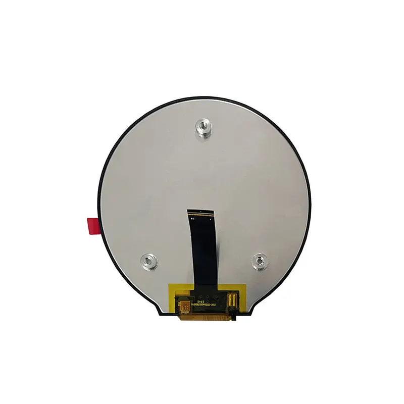
The production envelope is approximately 110.00 × 113.49 × 7.80 mm, including the lower interface region. The active image area is 101.52 × 101.52 mm.
Provide controlled glass support, rear clearance and FPC space. Align the cover opening with the active area and include assembly tolerances.
Control FPC Routing
Follow the approved bend direction and minimum bend radius. Avoid sharp folding near the panel exit or loading the flex during assembly. Connector access and strain relief should be included in the first mechanical review.
Applications and Selection Boundaries
The High Brightness MIPI Round TFT Panel can be evaluated for industrial gauge clusters, smart-appliance dials, laboratory controls, audio interfaces, tabletop controllers and protected equipment HMIs.
Medical, automotive or exposed outdoor use requires system-level qualification. The component data does not establish medical certification, automotive grade, waterproofing, vibration resistance or finished-product sunlight readability.
Configuration and Customization
Branding, packaging and graphic customization are listed from 500 pieces. FPC geometry, interface mapping, cover lens, touch integration, bonding, luminance, backlight and mechanical changes require separate feasibility review.
Sample and standard-module quantities are confirmed independently. Any luminance or backlight change needs its own electrical, thermal and lifetime validation.
Procurement Checklist
Confirm before sample approval:
- Native 720 × 720 timing and circular safe area
- MIPI lane count, mapping, polarity and operating mode
- Complete 39-pin definition and FPC orientation
- 1.8 V I/O and +6.3 V / −6.3 V bias requirements
- Reset, tearing-effect and command behavior
- LED voltage, current tolerance and dimming
- 800 cd/m² minimum luminance target
- Active-area and enclosure alignment
- Cover-lens and touch requirements
- Temperature qualification, sample criteria and annual demand

FAQ
About 4 Inch High Brightness MIPI Round TFT Panel
What must be checked before connecting the 39-pin interface?
Does the same MIPI lane count guarantee host compatibility?
How should 720 × 720 artwork be prepared?
Is 800 cd/m² minimum sufficient for direct sunlight?
Is touch included?
Freya Yang
+86 18318948097