Freya Yang
+86 18318948097
+852 62667476
7 Inch Vehicle Gauge RGB Display Module for Instrument Clusters
Model P/N
Size
Resolution
Brightness
Viewing Angle
Connector Type
Operating Temp
Overall(mm)
huisoar
HS7A1609V1
Brand
Panel Size (inch)
Model P/N
Resolution
Brightness (nits)
Viewing Angle
Response Time
Overall (mm)
Active Area (mm)
Refresh Rate
Display Colors
Panel Type
Connector Type
Operating Temp
Touchscreen Type
Storage Temp
Work Mode
Pixel Format
Designed For
7 Inch Vehicle Gauge RGB Display Module for Instrument Clusters
This landscape TN module combines an 800 × 480 canvas, 24-bit parallel RGB data and project-specific touch options for compact gauge interfaces.
Product Summary
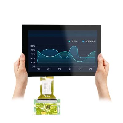
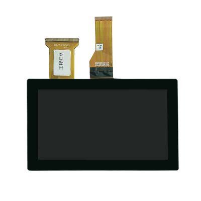
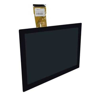
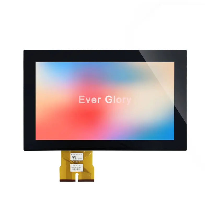
The Vehicle Gauge RGB Display Module is a 7-inch embedded TFT-LCD for instrument clusters, equipment status panels and compact control interfaces that use a conventional landscape layout.
Its 800 × 480 resolution supports speed indicators, battery information, operating modes, warning icons and menu content without requiring a high-resolution graphics platform. The 24-bit RGB connection provides a direct parallel display path for compatible embedded processors and controller boards.
The panel uses TN normally-white transmissive technology with a defined 12 o’clock viewing direction. Touch functionality must be selected as part of the approved project configuration rather than assumed from the display-panel specification alone.
Key Specifications
| Specification | Value |
|---|---|
| Display size | 7 inch |
| Resolution | 800 × 480 pixels |
| Active area | 153.84 × 85.63 mm |
| Overall dimensions | 166.5 × 101.6 mm |
| Display technology | TN TFT-LCD |
| Display mode | Normally white, transmissive |
| Interface | 24-bit parallel RGB |
| Connector | 40 pins |
| Viewing direction | 12 o’clock |
| Luminance | 280 cd/m² typical; 230 cd/m² minimum |
| Display colors | 16.7M colors |
| Backlight | 21 white LEDs |
| Luminance uniformity | 80% minimum |
| Operating temperature | −10°C to +60°C |
| Storage temperature | −20°C to +70°C |
| Touch status | Project-specific |
800 × 480 Gauge Interface Planning
Native Landscape UI Structure
The 800 × 480 canvas provides a familiar landscape format for embedded gauge and status interfaces.
A practical UI can divide the screen into zones for:
- Primary speed or operating value
- Battery or fuel status
- Warning indicators
- Direction and navigation prompts
- Operating mode
- Temperature values
- Trip or runtime information
- Maintenance alerts
- Menu navigation
- Connectivity status
Preparing graphics at the native resolution helps maintain icon edges and text placement without avoidable scaling.
Vehicle Status and Warning Layouts
Instrument-cluster content should prioritize information hierarchy rather than filling the entire screen with equal-weight graphics.
The primary operating value should remain visually dominant. Warning symbols need sufficient contrast and separation, while secondary status data should not compete with safety-critical information.
UI validation should cover:
- Day and night color themes
- Warning-color differentiation
- Minimum text size
- Viewing distance
- Installation angle
- Glance readability
- Startup screen behavior
- Fault-state presentation
- Language expansion
- Touch and non-touch control paths
Vehicle Gauge RGB Display Module Integration
The Vehicle Gauge RGB Display Module uses a 24-bit parallel RGB interface.
24-Bit Parallel RGB Qualification
A processor or controller must generate the approved pixel data and timing signals for the display.
Qualification should confirm:
- Native 800 × 480 timing
- Pixel clock
- Red, green and blue data mapping
- Data width
- Horizontal synchronization
- Vertical synchronization
- Data-enable behavior
- Clock polarity
- Scan direction
- Display-enable requirements
- Logic voltage
- Ground distribution
- Cable or FPC length
A 24-bit RGB label does not establish timing, pinout or voltage compatibility with a host board.
40-Pin Host and Cable Review
The visible pin drawing includes RGB data groups and display-control signals, but the complete approved pin definition must control the final cable and PCB design.
Before schematic release, compare:
- Pin numbering direction
- Connector orientation
- Contact side
- RGB bit order
- Clock and synchronization pins
- Ground positions
- Backlight pins
- Display-enable signals
- Unused pins
- FPC insertion direction
- Cable bend radius
- Connector retention
A matching 40-pin count alone is insufficient evidence of compatibility.
TN Viewing Direction and Mounting
The display uses TN normally-white transmissive operation with a 12 o’clock viewing direction.
This means the panel should be evaluated in the intended installation orientation rather than treated as an all-angle display.
A 12 o’clock viewing direction must be validated against the installed operator position.
Evaluation should include:
- Driver eye position
- Panel tilt
- Dashboard height
- Landscape orientation
- Dark-state appearance
- Gray-scale behavior
- Warning-icon visibility
- Side viewing positions
- Reflections from cover glass
- Day and night interface themes
Rotating the module or installing it below the intended line of sight can change perceived contrast and gray-scale performance.
Optical and Backlight Boundaries
The module provides 280 cd/m² typical luminance, with 230 cd/m² minimum indicated for the standard configuration.
This luminance is suitable for controlled indoor environments, equipment cabins and instrument housings where the optical stack and ambient lighting are managed. It should not be described as a sunlight-readable panel without finished-system testing.
The display includes 21 white LEDs, with a 60 mA current reference and 20 mA-per-LED notation. The approved backlight circuit must establish:
- Forward voltage
- Series and parallel arrangement
- Current regulation
- Enable control
- Dimming method
- Startup behavior
- Thermal loading
- Driver efficiency
The listed 80% minimum luminance uniformity should be considered together with cover-lens transmission and viewing angle.
A 280 cd/m² panel is not intended to prove direct-sun visibility in a finished product.
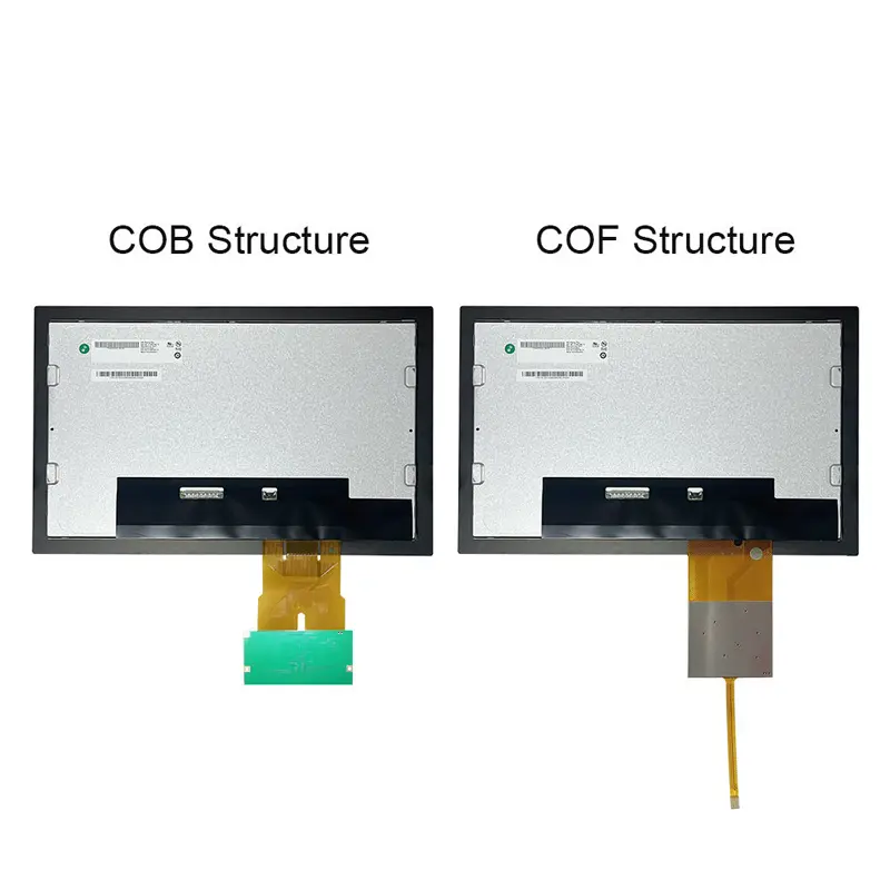
Touch Configuration and Front-Stack Design
Confirming the Touch Build
Touch functionality is project-specific.
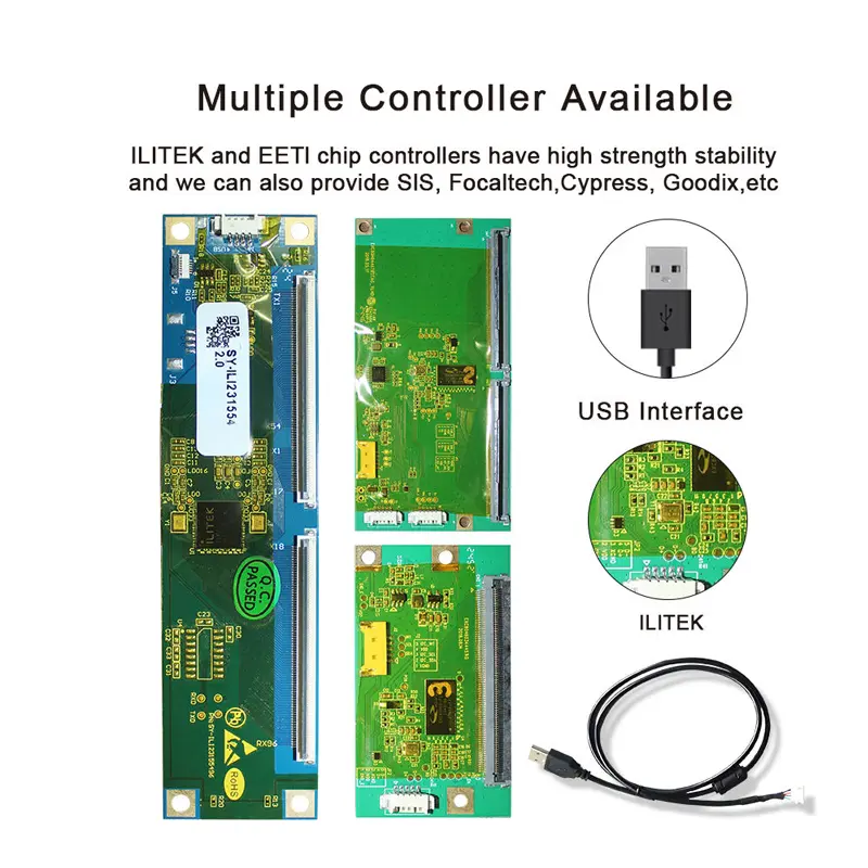
A complete build may include a touch panel and an I²C signal group, but procurement and engineering teams must confirm whether the ordered part includes:
- Touch sensor
- Touch controller
- Cover lens
- Bonding adhesive
- Touch FPC
- Touch firmware
- Connector
- Touch cable
- Surface treatment
- Optical bonding
Touch capability is project-specific unless the approved bill of materials explicitly includes the touch panel and controller.
Touch Interface and Cover-Lens Review
When touch is required, confirm:
- Touch-controller model
- I²C address
- Logic voltage
- Interrupt polarity
- Reset timing
- Firmware version
- Number of touch points
- Cover-lens thickness
- Decorative printing
- Touch active area
- Edge margin
- Glove requirement
- Stylus requirement
- Water-handling requirement
- EMC validation
- Bonding method
The display RGB interface and touch interface are separate engineering paths. A host that supports the LCD timing does not automatically support the selected touch controller.
Mechanical and Environmental Integration
The active display area is 153.84 × 85.63 mm, while the panel outline is 166.5 × 101.6 mm.
Mechanical release should use the approved drawing rather than rounded seven-inch reference dimensions.
Review:
- Visible window size
- Bezel overlap
- Active-area centering
- Panel thickness
- Rear-component clearance
- FPC position
- FPC bending direction
- Connector clearance
- Touch-FPC routing
- Housing flatness
- Mounting pressure
- Adhesive width
- Thermal expansion
- Service access
The panel operates from −10°C to +60°C and stores from −20°C to +70°C. These values apply to the component and do not establish the operating range of the controller board, touch assembly, cover lens, adhesive or completed instrument cluster.
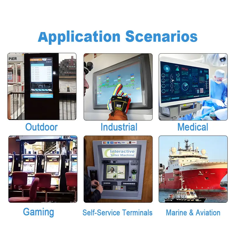
Application Scenarios
Vehicle Gauges
The landscape format can support speed, battery state, warnings, operating modes and trip information in compact gauge assemblies.
Instrument Clusters
The panel can serve as the visual component of an instrument cluster after host timing, viewing direction, enclosure and qualification requirements are validated.
Equipment Status Panels
Embedded machinery can use the display for operating values, alarms, icons and service menus.
Appliance Control Interfaces
The 800 × 480 format can support appliance status, settings and operating sequences where a landscape interface is preferred.
Indoor Terminals
The moderate luminance and compact footprint fit terminals used under controlled ambient lighting.
Custom Touch Interfaces
A project-specific touch stack can be reviewed where menu navigation or direct control is required.
The application references do not establish automotive certification, vibration grade, waterproof performance or regulatory approval for the finished device.
Customization Scope
Project review can include:
- Touch-panel integration
- Touch-controller selection
- I²C touch interface
- Cover-lens dimensions
- Decorative printing
- Custom shapes
- Surface treatment
- Optical bonding
- Air bonding
- FPC geometry
- Connector adaptation
- Cable routing
- Backlight adjustment
- UI orientation
- Mounting fixtures
- Branding
- Packaging
Custom configurations are generally reviewed from 500 pieces, subject to tooling requirements, material availability and the requested specification. Sample and standard-module quantities are confirmed separately.
Procurement Checklist
Submit:
- Approved display datasheet
- Approved mechanical drawing
- Native 800 × 480 timing
- Pixel clock
- Sync and data-enable requirements
- Clock polarity
- 24-bit RGB data mapping
- Complete 40-pin pinout
- Logic voltage
- Display-enable definition
- Backlight voltage
- Backlight current
- Backlight topology
- Dimming requirement
- Connector pitch
- Connector contact side
- FPC direction
- Viewing orientation
- Enclosure drawing
- Visible window
- Mounting method
- Touch-panel requirement
- Touch-controller model
- Touch interface
- Cover-lens drawing
- Surface treatment
- Bonding requirement
- Operating-temperature target
- Sample quantity
- Annual demand
- Project schedule
FAQ
About 7 Inch Vehicle Gauge RGB Display Module
What must be checked before connecting a 24-bit RGB host?
How does the 12 o’clock viewing direction affect installation?
Is a capacitive touch panel included in every configuration?
Is 280 cd/m² suitable for outdoor use?
Which details are required before releasing enclosure tooling?
Freya Yang
+86 18318948097