
Freya Yang
+86 18318948097
+852 62667476
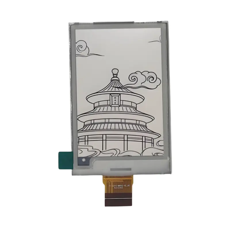
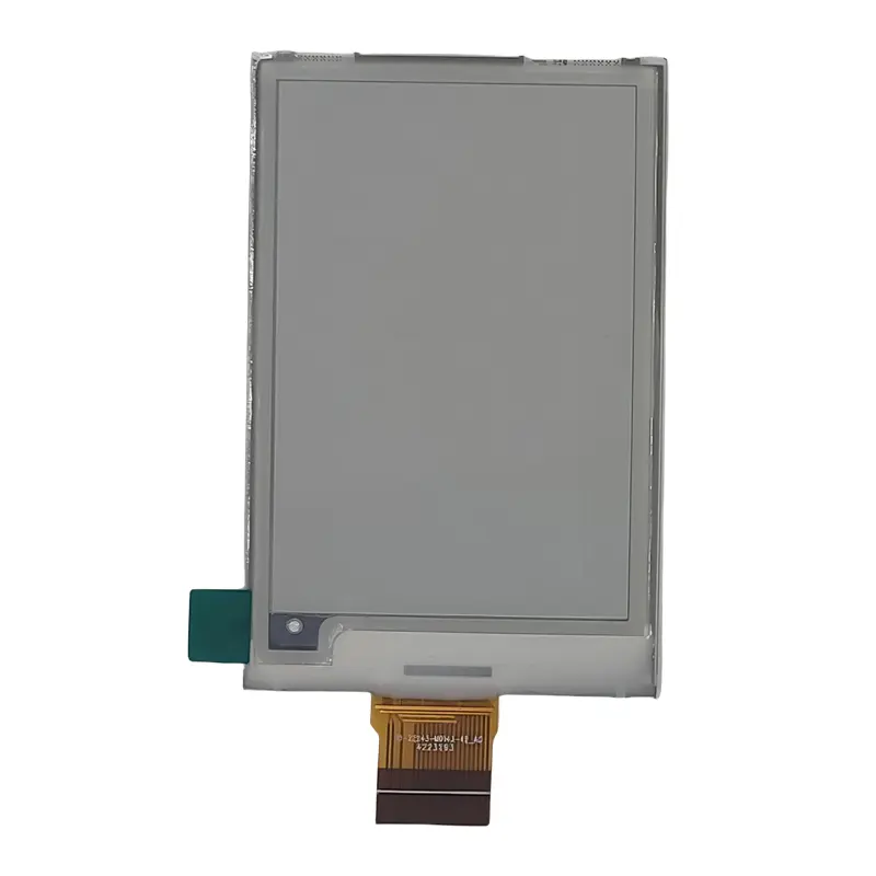
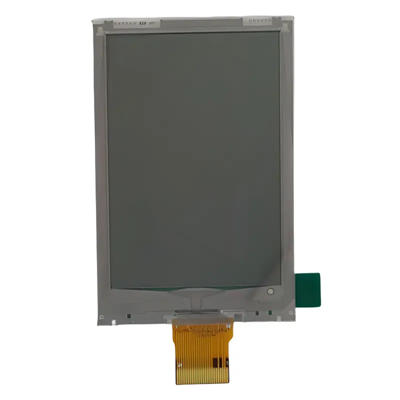
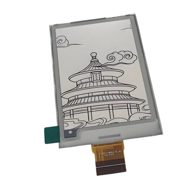
2.7 Inch Smart Card E Ink Display Panel for Work Cards
Model P/N
Size
Resolution
Brightness
Viewing Angle
Connector Type
Operating Temp
Overall(mm)
huisoar
HS02701-M014F-I
Brand
Panel Size (inch)
Model P/N
Resolution
Viewing Angle
Response Time
Overall (mm)
Active Area (mm)
Refresh Rate
Display Colors
Panel Type
Connector Type
Operating Temp
Touchscreen Type
Storage Temp
Work Mode
Pixel Format
Input Voltage (V)
Operating Environment
Designed For
2.7 Inch Smart Card E Ink Display Panel for Work Cards
Built for smart-card and work-card interfaces, this 2.7-inch electronic-paper panel provides a 264 × 176 image format in a slim 1.0 mm panel body.
The Smart Card E Ink Display Panel is a compact EPD component for card-based information devices, electronic price tags, work cards, messenger cards, and smart cards. It combines a portrait mechanical format, a 38.19 × 57.29 mm active area, a 24-pin bottom FPC, and a listed operating range of 0°C to +50°C. Integration should begin with the approved color version, complete pin definition, controller and waveform package, and the final card or enclosure drawing.
Product Summary
The panel uses a passive-matrix electronic-paper format with 264 × 176 dots. The mechanical drawing presents the active image area in portrait orientation, measuring 38.19 mm horizontally and 57.29 mm vertically. This geometry can support names, identifiers, short messages, pricing, status fields, compact icons, and simple card-based information layouts.
Plan Content at the Native Raster
Artwork should be prepared for the native 264 × 176 matrix rather than scaled from a conventional LCD aspect ratio. Text size, line spacing, borders, QR-style graphics, and icon contrast should be checked on an actual sample because electronic-paper rendering and refresh behavior depend on the ordered panel, controller, waveform, and color version.
Approve the Color Version Before Artwork Release
The product family lists black/white and black/white/red configurations. These should be treated as separate ordered versions, not as a software-selectable color mode on one universal panel. Red artwork requires an approved three-color panel and the correct controller, lookup table, and waveform package.
Key Specifications
| Parameter | Specification |
|---|---|
| Display size | 2.7 inch |
| Display technology | E Ink / EPD |
| Display mode | Passive matrix |
| Resolution | 264 × 176 dots |
| Active area | 38.19(H) × 57.29(V) mm |
| Panel-body outline | 45.80 ± 0.20 × 70.42 ± 0.20 × 1.00 ± 0.10 mm |
| Color versions | Black/white or black/white/red |
| Viewing angle | Nearly 180° listed |
| Connector | 24-pin bottom FPC |
| FPC pitch | 0.50 mm |
| Operating temperature | 0°C to +50°C |
| Touch | Not confirmed |
| Front light | Not confirmed |
| Controller and interface protocol | Require ordered-revision confirmation |
Card Integration with the Smart Card E Ink Display Panel
Qualify the Complete 24-Pin FPC
The drawing identifies 24 contacts on a 0.50 mm pitch, a 12.50 ± 0.10 mm FPC width, and a defined contact side with stiffener. A 24-pin FPC does not establish SPI, voltage, signal order, timing, or controller compatibility. Engineering approval should use the complete pin table, connector specification, FPC contact orientation, and bend requirements for the ordered revision.
Separate Panel Geometry from FPC Clearance
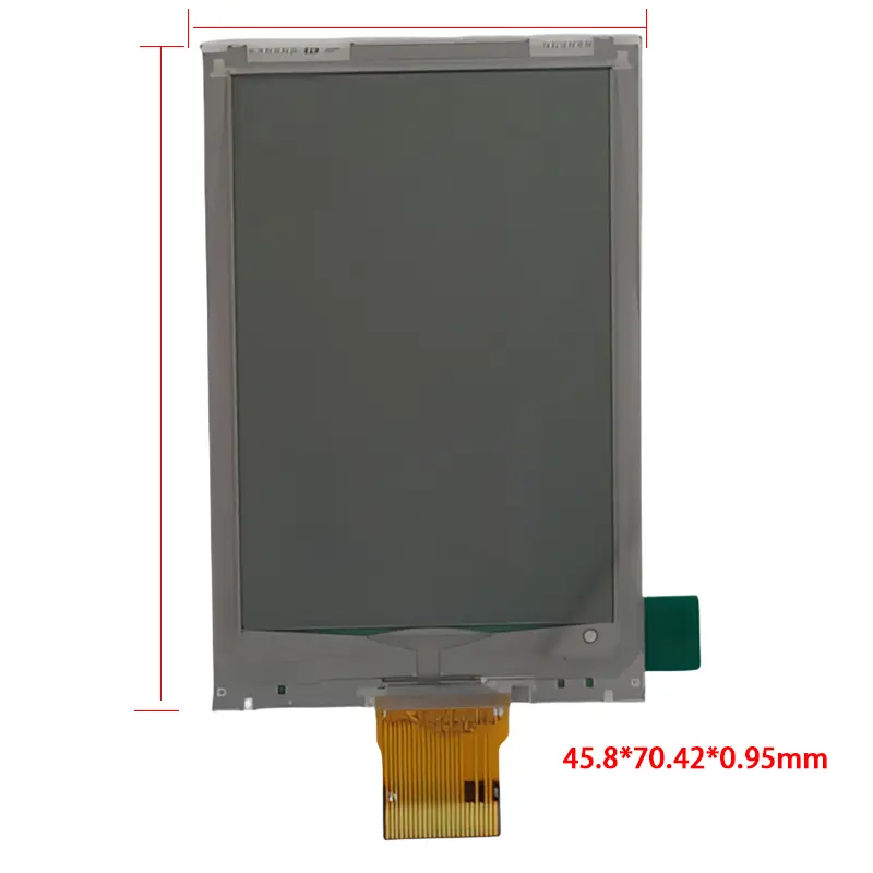
The 45.80 × 70.42 × 1.00 mm value describes the panel body. The flexible tail extends below that body and must be included in the product envelope, connector location, bend radius, assembly sequence, and service-clearance review. Housing release should use the full mechanical drawing rather than the panel-body dimensions alone.
Mechanical Fit for Thin Card and Label Devices
Active Area and Border Planning
The 38.19 × 57.29 mm active area sits within a 45.80 × 70.42 mm panel body. The difference between those dimensions creates the non-active border needed for the display structure and FPC exit. Window graphics, adhesive areas, protective overlays, and printed borders should be aligned to the approved drawing.
Thickness and Stiffener Details
The panel thickness is listed as 1.00 ± 0.10 mm. The drawing separately shows FPC and stiffener thickness references, so the card cavity or enclosure should not assume one uniform thickness across the entire assembly. Pressure points over the display edge, tail transition, contacts, and stiffener should be avoided during mechanical design.
Temperature and Update Planning
The listed operating range is 0°C to +50°C. This range should control update testing unless an alternate temperature grade is supplied. It does not support a claim that the panel can refresh below 0°C, and no storage range is confirmed for the assigned product.
Electronic-paper update time, full-refresh behavior, partial-refresh support, flashing, ghosting limits, image retention, and power consumption require the exact controller and waveform documentation. Do not transfer these values from another 2.7-inch panel solely because the resolution and outline appear similar.
Applications and Product Boundaries
The Smart Card E Ink Display Panel can be evaluated for electronic price tags, work cards, messenger cards, smart cards, reusable information cards, and compact identification interfaces. The component is a display panel, not a complete wireless price tag, NFC card, access-control credential, battery-powered badge, or finished reader.
Any complete card product still requires a host controller, power architecture, communication method, firmware, enclosure or laminate structure, and an approved way to connect and drive the 24-pin FPC.
Customization and Version Control
Projects may review color version, FPC geometry, connector definition, artwork, logo treatment, front overlay, enclosure adaptation, and controller or waveform support. Logo customization is generally reviewed from 5,000 pieces. Other modifications require separate feasibility, tooling, material, and quantity confirmation.
For a modified Smart Card E Ink Display Panel, the sample approval record should identify the exact supplier revision, black/white or black/white/red build, pin map, controller, waveform files, active area, body outline, FPC orientation, contact side, and operating-temperature requirement.
Procurement Checklist
- Confirm the assigned model and supplier revision.
- Select black/white or black/white/red before artwork approval.
- Submit native 264 × 176 artwork and intended display orientation.
- Obtain the complete 24-pin pinout and connector definition.
- Confirm interface protocol, voltage rails, reset, busy, data, command, and timing requirements.
- Obtain the approved controller, lookup-table, and waveform package.
- Approve the 38.19 × 57.29 mm active area and 45.80 × 70.42 × 1.00 mm panel body.
- Include the FPC tail, contact side, stiffener, connector, and bend clearance in the mechanical design.
- Confirm operating and storage conditions, refresh target, sample quantity, annual demand, and acceptance criteria.
FAQ
About 2.7 Inch Smart Card E Ink Display Panel
What must be checked before connecting the 24-pin FPC?
How should the black/white and black/white/red versions be selected?
Is this panel a complete smart card or electronic price tag?
Which dimensions should control the enclosure or card cavity?
Can the panel be updated below 0°C?
Freya Yang
+86 18318948097
