
Freya Yang
+86 18318948097
+852 62667476
4.2 Inch Low Power E-Paper Display Module for OEM R&D Teams
Model P/N
Size
Resolution
Brightness
Viewing Angle
Connector Type
Operating Temp
Overall(mm)
empty
HS042EK-1
Brand
Panel Size (inch)
Model P/N
Resolution
Brightness (nits)
Viewing Angle
Contrast Ratio
Response Time
Overall (mm)
Active Area (mm)
Display Colors
Panel Type
Connector Type
Operating Temp
Touchscreen Type
Storage Temp
Work Mode
Weight (g)
Operating Environment
Designed For
4.2 Inch Low Power E-Paper Display Module for OEM R&D Teams
A 400 × 300 four-color E-paper module gives OEM R&D teams a thin, lightweight platform for low-update embedded information interfaces.
Product Summary
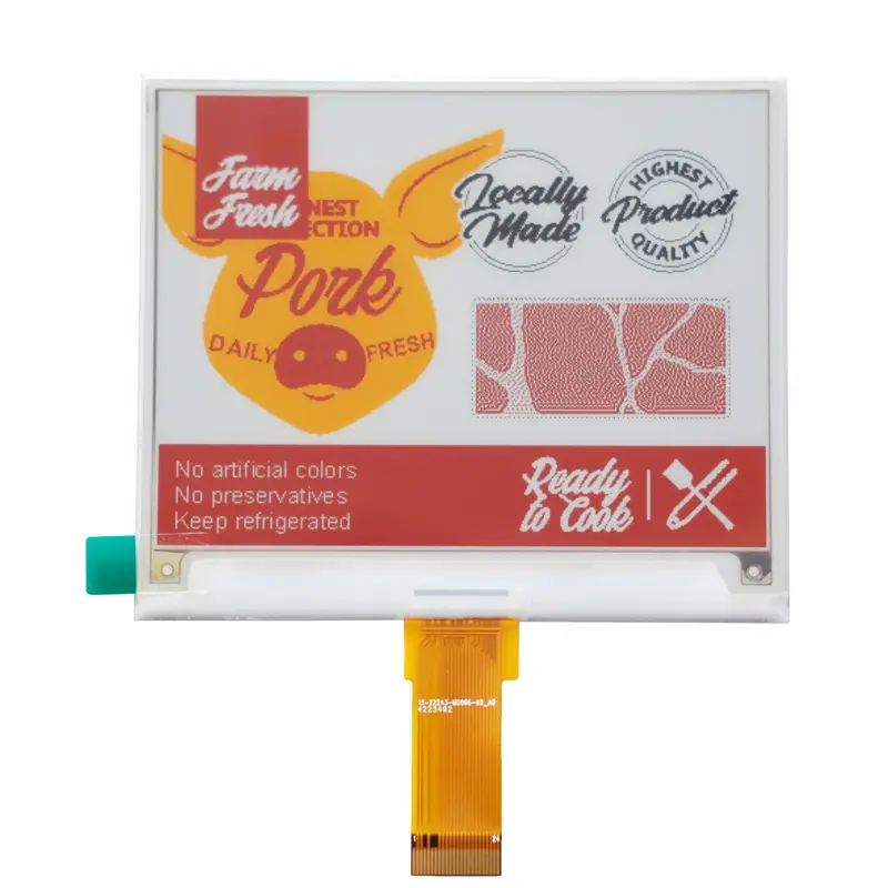
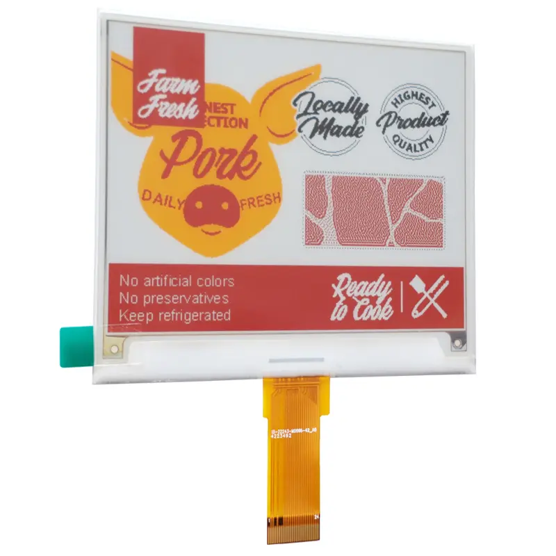
The 4.2 Inch Low Power E-Paper Display Module for OEM R&D Teams is a compact electronic-paper component for products that need clear, structured information without the display behavior of a continuously changing TFT interface. Its 400 × 300 pixel format provides useful space for labels, status values, icons, identification information, simple diagrams and other low-update content.
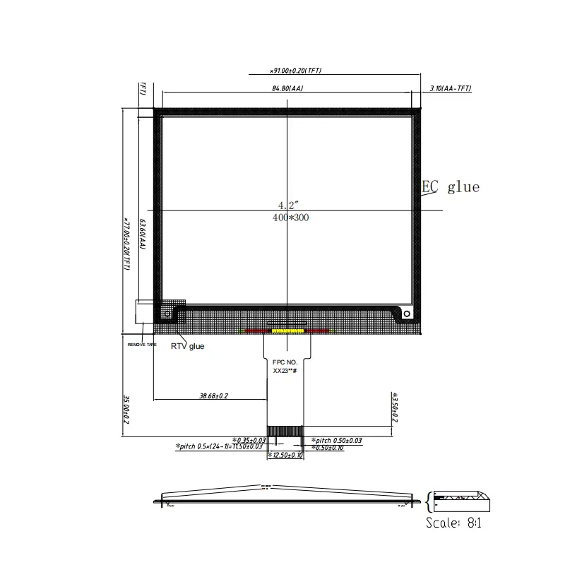
The module combines an 84.80 × 63.60 mm active area with a 91.0 × 77.0 × 0.93 mm outline and a module weight of 15.5 ± 0.5 g. The selected configuration provides black, white, red and yellow output, allowing designers to create clear visual hierarchy while keeping the display architecture focused on information rather than multimedia.
Key Specifications
| Specification | Value |
|---|---|
| Display size | 4.2 inches |
| Resolution | 400 × 300 pixels |
| Display technology | E-paper / EPD |
| Selected colors | Black, white, red and yellow |
| Active area | 84.80 × 63.60 mm |
| Pixel pitch | 0.212 × 0.212 mm |
| Pixel configuration | Rectangle |
| Module outline | 91.0 × 77.0 × 0.93 mm |
| Module weight | 15.5 ± 0.5 g |
Why Low-Power E-Paper Fits OEM R&D
E-paper is most useful when the finished product primarily presents information that remains stable between updates. That operating pattern is fundamentally different from a TFT display used for video, animation or continuously changing graphical interfaces.
For OEM teams, this makes the module relevant to battery-conscious and compact products where display behavior can be designed around periodic content changes rather than continuous visual activity.
Information Retention for Low-Update Interfaces
The 400 × 300 raster gives developers enough native image area for status pages, equipment identifiers, inventory information, values, schedules, simple menus and compact graphics.
Before firmware and power architecture are finalized, the expected update interval should be defined. A device that changes content only occasionally has a different controller and energy profile from one expected to update repeatedly throughout the day.
Four-Color Content Planning
The selected version uses black, white, red and yellow.
Artwork should therefore be designed specifically around these supported color states instead of being treated as ordinary full-color RGB content. Black and white can handle the primary information structure, while red and yellow can be reserved for warnings, priorities, categories or highlighted states.
The native 400 × 300 canvas should be approved before the UI or label artwork is released.
Mechanical Integration for a 4.2-Inch Module
Mechanical fit is one of the strongest confirmed areas for early-stage development because the active area, outline, pixel pitch and module weight are clearly defined.
Active Area Versus Module Outline
The visible active area is 84.80 × 63.60 mm, while the module outline is 91.0 × 77.0 mm.
These dimensions should not be treated as interchangeable. The active area controls the visible content window, while the larger module dimensions affect retention, adhesive zones, housing clearance and front-window design.
The 0.212 × 0.212 mm pixel pitch also provides a fixed reference for native artwork and mechanical alignment.
Thin Profile and Module Weight
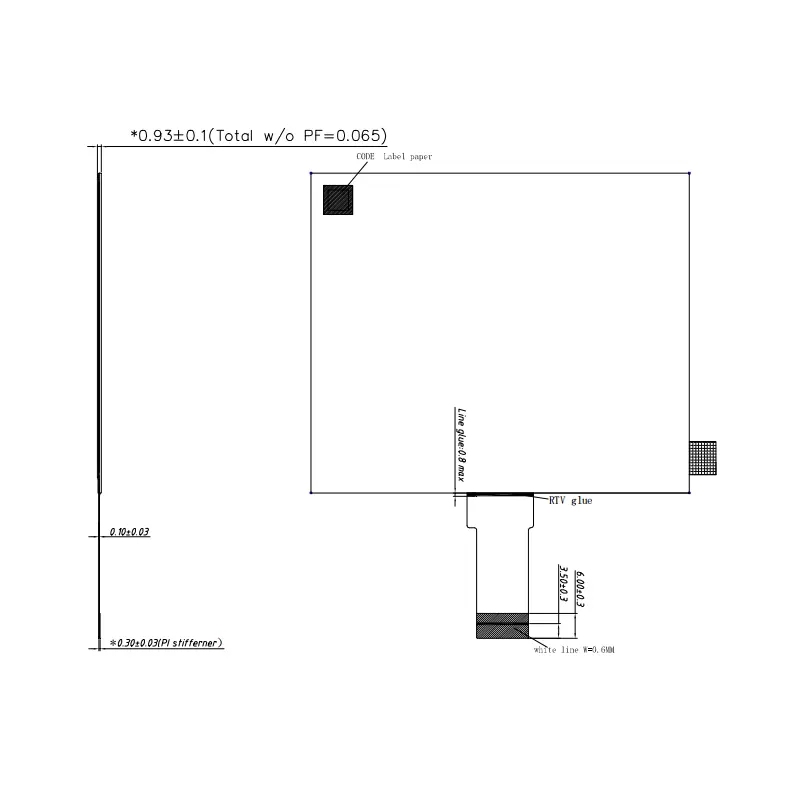
The module outline includes a 0.93 mm thickness, giving designers a thin display stack for compact housings.
The module itself weighs 15.5 ± 0.5 g. This is the correct figure for display-mass planning. A separate 0.5 kg value associated with shipping refers to gross package weight and should never be used for enclosure load calculations.
Flex-tail routing and local component clearance still need to be checked against the approved mechanical drawing before tooling is released.
Host Qualification for the 4.2 Inch Low Power E-Paper Display Module for OEM R&D Teams
Electrical release should not be based only on the visible flex connection or the fact that the display uses electronic-paper technology.
The exact production revision must be matched to the approved connector, interface, controller and waveform documentation.
Interface and FPC Definition
A flex-tail connection does not establish communication protocol or electrical compatibility.
Before the host PCB is frozen, obtain the complete connector drawing and confirm pin count, contact side, pitch, orientation, signal assignments, logic levels, required display-drive voltages, timing and power behavior.
Matching physical dimensions alone is not enough to establish compatibility between the module and a controller platform.
Controller and Waveform Requirements
Electronic-paper operation also depends on the correct controller and waveform resources for the ordered display revision.
Before firmware release, confirm the controller IC or supported controller architecture, command set, LUT or waveform package, reset and busy behavior, full-refresh method, any supported partial-refresh behavior and the required initialization sequence.
These items should come from approved production documentation rather than being inferred from another 4.2-inch display.
Refresh and Power Validation
For the 4.2 Inch Low Power E-Paper Display Module for OEM R&D Teams, a numerical battery-life claim should only be made after exact update-power and controller data are available.
A finished product power budget can depend on refresh frequency, sleep behavior, controller electronics, host MCU activity, wireless communication and the rest of the system architecture.
The useful engineering question is therefore not simply whether the display is described as low power. The more important question is how often the actual device needs to update and what the approved production module requires during those updates.
Best-Fit Application Direction
Portable and Embedded Information Interfaces
This module is a practical candidate for portable instruments, reusable identifiers, smart labels, compact equipment-information panels, handheld status devices and other embedded products that present structured information for relatively long periods.
Its 400 × 300 resolution and 84.80 × 63.60 mm active area give OEM designers a usable information surface without requiring a large enclosure.
The low module weight and 0.93 mm profile can also help where front-panel depth and overall product mass matter.
When Another Display Technology Is More Suitable
This module should not be selected simply because low power is desirable.
A product requiring fluid animation, video, very frequent graphics changes or a conventional continuously interactive UI may be better served by another display technology.
Likewise, touch, front illumination, environmental sealing, wireless communication and specific outdoor or medical qualification should be treated as separate system requirements unless they are confirmed for the ordered assembly.
Customization and Procurement
Branding, packaging and graphic customization are generally reviewed from 500 pieces.
Requests involving FPC geometry, connector definition, electrical interface, controller or waveform support, ordered color configuration, front-window design or enclosure adaptation require project-specific feasibility review.
Sample and standard-module quantities should be confirmed separately from customized production quantities.
Procurement Checklist
Before releasing the 4.2 Inch Low Power E-Paper Display Module for OEM R&D Teams, confirm the approved production revision, exact black/white/red/yellow configuration, native 400 × 300 artwork orientation, 84.80 × 63.60 mm active area, 91.0 × 77.0 × 0.93 mm outline and 15.5 ± 0.5 g module weight.
Also obtain the complete FPC and connector drawing, pin assignment, electrical interface, logic and display-drive voltages, timing, controller documentation, LUT or waveform package, full- and partial-refresh behavior, refresh time, update and sleep power, operating and storage limits, front-light or touch requirements, front-window design, sample criteria, annual quantity and project schedule.
FAQ
About 4.2 Inch Low Power E-Paper Display Module
What must be confirmed before the host PCB is designed?
How should four-color artwork be prepared for this module?
Which dimensions matter most when designing the enclosure?
What information is required before estimating battery life?
Freya Yang
+86 18318948097
