
Freya Yang
+86 18318948097
+852 62667476
9.35 Inch Rearview Mirror LCD Module for Vehicle HMI
Model P/N
Size
Resolution
Brightness
Viewing Angle
Connector Type
Operating Temp
Overall(mm)
huisoar
HS935003B0
Brand
Panel Size (inch)
Model P/N
Resolution
Brightness (nits)
Viewing Angle
Contrast Ratio
Response Time
Overall (mm)
Active Area (mm)
Refresh Rate
Display Colors
Panel Type
Connector Type
Operating Temp
Touchscreen Type
Storage Temp
Work Mode
Pixel Format
Control Type
Operating Environment
Designed For
9.35 Inch Rearview Mirror LCD Module for Vehicle HMI
This slim IPS module combines a native 440 × 1920 vertical canvas, 1000 cd/m² luminance, and 40-pin MIPI connectivity for narrow vehicle interfaces.
Product Summary
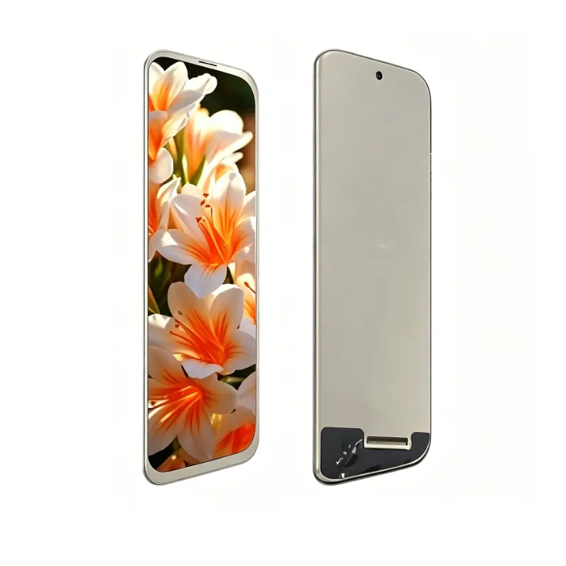
The Rearview Mirror LCD Module provides a tall, narrow image area for digital-mirror interfaces, electric-mobility instrument panels, motorcycle dashboards, status displays, and other vehicle-HMI designs where conventional landscape screens do not fit efficiently.
Its 440 × 1920 resolution supports vertically arranged camera imagery, warnings, navigation prompts, speed information, status indicators, and menu elements. The 9.35-inch module combines IPS viewing, 1000 cd/m² typical luminance, a 40-pin MIPI interface, and a compact 64.48 × 246.15 × 4.50 mm outline.
The standard configuration is non-touch. Interaction can be handled through steering controls, buttons, a rotary controller, a separate touch surface, or another host interface.
Key Specifications
| Specification | Value |
|---|---|
| Display size | 9.35 inch |
| Resolution | 440 × 1920 pixels |
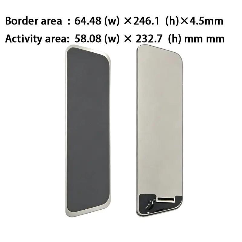
| Active area | 58.08 × 232.70 mm |
| Module outline | 64.48 × 246.15 × 4.50 mm |
| Panel technology | a-Si IPS TFT-LCD |
| Optical mode | Transmissive |
| Luminance | 1000 cd/m² typical |
| Contrast ratio | 800:1 typical |
| Viewing angle | 80°/80°/80°/80°, L/R/U/D |
| Display colors | 16.2M colors |
| Interface | 40-pin MIPI |
| Driver IC identifier | ICN9707 |
| Backlight | WLED |
| Touch status | Non-touch |
| Operating temperature | −20°C to +70°C |
| Storage temperature | −30°C to +80°C |
440 × 1920 Vertical UI Design
Native Portrait Raster
The 440 × 1920 raster is intended for interfaces that use height more efficiently than width. It supports a continuous vertical presentation without forcing a standard landscape layout into a narrow enclosure.
Potential content regions include:
- Rear-camera image
- Blind-zone or proximity indicator
- Speed and vehicle status
- Navigation instruction
- Warning messages
- Battery or fuel level
- Driving-mode information
- Temperature or environment data
- Communication status
- Menu and settings areas
The panel should be driven at its native raster whenever practical. Native output preserves text proportions, icon clarity, line weight, and the intended spacing between content regions.
Mirror and Instrument Content Zones
The active area measures 58.08 × 232.70 mm. UI development should account for the cover opening, decorative mask, mounting tolerance, and any hidden edge area.
Critical warnings and camera information should remain inside a validated safe zone. Character height, viewing distance, glance duration, icon recognition, and day/night color themes should be reviewed using the completed assembly.
IPS Viewing and 1000 cd/m² Optical Performance
Bright-Cabin Readability Boundary
The panel provides 1000 cd/m² typical luminance. This supports evaluation for bright vehicle cabins, mirror-style interfaces, motorcycles, electric-mobility instruments, and equipment installed near windows.
A 1000 cd/m² panel does not by itself establish finished-system daylight readability behind front glass.
Completed-system visibility depends on:
- Cover-glass transmission
- Internal and external reflections
- Anti-glare or anti-reflective treatment
- Optical bonding
- Installation angle
- Vehicle-glass reflections
- UI colors and contrast
- Backlight dimming
- Panel temperature
- Enclosure shading
- Thermal management
The complete optical stack should be tested under the actual target lighting.
Viewing Angle and Contrast
The IPS panel provides 80° viewing in the left, right, upper, and lower directions. This supports installations where the operator does not view the screen directly along its centerline.
The 800:1 typical contrast ratio supports differentiation between camera imagery, text, icons, warnings, and darker interface backgrounds. Finished contrast remains dependent on ambient light and the cover construction.
40-Pin MIPI Integration
Host Qualification
The module uses a 40-pin MIPI display interface.
A 40-pin MIPI connector does not guarantee lane, timing, voltage, initialization, or pin compatibility with another panel.
Before PCB or controller release, confirm:
- Native 440 × 1920 timing
- MIPI DSI lane count
- Lane mapping
- Command or video mode
- Link rate
- Pixel format
- Complete 40-pin assignment
- Connector pitch
- Contact side
- Pin-1 orientation
- Panel power rails
- Logic voltage
- Reset and enable behavior
- Backlight-driver requirements
- Dimming-control method
- FPC routing and bend radius
The approved model-specific interface document should control electrical integration.
ICN9707 Documentation Boundary
ICN9707 is identified for the display configuration. The part number alone does not establish:
- The required MIPI DSI lane count
- Command or video mode
- Register values
- Initialization sequence
- Power sequencing
- Sleep and wake commands
- Gamma programming
- Host compatibility
- Backlight behavior
Engineering release should use the approved initialization package, timing table, power specification, and complete pin map for the ordered version.
A host without compatible MIPI DSI output requires a suitable bridge or controller. HDMI, LVDS, eDP, USB video, SPI, and parallel RGB do not connect directly without conversion.
Mechanical Fit of the Rearview Mirror LCD Module
Slim Enclosure Planning
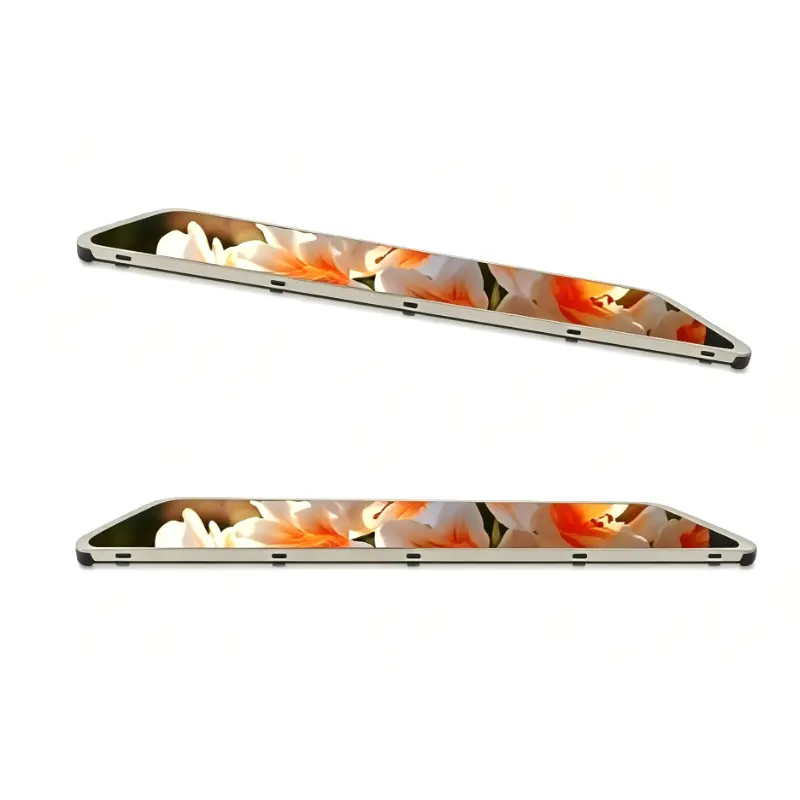
The module outline is 64.48 × 246.15 × 4.50 mm. Its active area is 58.08 × 232.70 mm.
Mechanical review should cover:
- Front opening
- Active-area alignment
- Corner shape
- Bezel overlap
- Decorative mask
- Rear clearance
- FPC location
- FPC exit direction
- Bend radius
- Mounting pressure
- Cover-glass stack
- Adhesive thickness
- Thermal clearance
- Service-removal path
Use the approved mechanical drawing before enclosure tooling, cover printing, bracket release, or adhesive-die cutting.
FPC and Rear Clearance
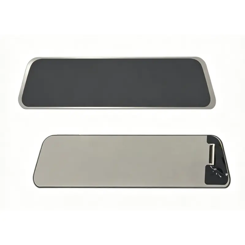
The product image shows a compact rear connection area near one end of the module. The final assembly must avoid forcing the FPC against the housing or creating a sharp fold near the bonded connection.
Prototype review should include:
- FPC contact-side verification
- Pin-1 direction
- Cable retention
- Bend radius
- Strain relief
- Rear-component clearance
- Adhesive compression
- Panel flatness
- Thermal expansion
- Vibration from the final equipment
Temperature and Application Qualification
The panel supports operation from −20°C to +70°C and storage from −30°C to +80°C.
These component limits do not independently establish:
- Automotive qualification
- Motorcycle qualification
- Vehicle safety compliance
- Waterproofing
- Dust protection
- Vibration resistance
- Shock resistance
- UV resistance
- Condensation resistance
- EMC or ESD compliance
- Continuous-use lifetime
- Camera-system safety performance
Qualification should use the final host processor, MIPI interface, power system, backlight driver, front glass, enclosure, cable, mounting system, software, and thermal design.
Application and Configuration Review
The Rearview Mirror LCD Module can be evaluated for:
- Digital rearview-mirror interfaces
- Electric-vehicle auxiliary instruments
- Motorcycle dashboards
- Mobility-equipment status displays
- Narrow vehicle information panels
- Vertical camera-monitoring interfaces
- Specialized transport-equipment HMIs
- Industrial vertical status terminals
It is a display component rather than a complete mirror or camera system. The standard module does not automatically include:
- Camera
- Video decoder
- MIPI bridge
- Main controller
- Touch panel
- Cover glass
- Housing
- Power supply
- Automatic dimming sensor
- Application software
- Environmental sealing
Non-Touch Architecture
The standard module is non-touch. This is appropriate when:
- Input is handled through physical controls
- The display presents camera or status information
- A separate controller is used
- Touch is not desirable on the mirror surface
- The finished product requires a custom touch stack
- Front optical performance takes priority over direct interaction
Optional touch development requires a separately defined sensor, controller, interface, cover lens, optical stack, mechanical drawing, and firmware plan.
Configuration Scope
Project review can include:
- MIPI host matching
- Complete 40-pin definition
- Approved initialization package
- Custom FPC or extension cable
- MIPI bridge or controller board
- Front cover glass
- Anti-glare or anti-reflective treatment
- Optical bonding
- Optional touch development
- Enclosure adaptation
- Mounting support
- Brightness validation
- Thermal review
- Branding and printing
- Packaging
Custom configurations are generally reviewed from 500 pieces, subject to tooling requirements, material availability, and the requested specification. Sample and standard-module quantities are confirmed separately.
Procurement Checklist
Submit:
- Host processor or controller model
- Native 440 × 1920 timing
- MIPI DSI lane count
- Command or video mode
- Lane mapping
- Pixel format and link rate
- Complete 40-pin assignment
- Connector pitch and orientation
- Panel power rails
- Logic voltage
- Reset and enable requirements
- Approved initialization package
- Backlight-driver requirements
- Dimming method
- Approved mechanical drawing
- Enclosure opening
- FPC route and bend
- Front-glass specification
- Target finished-front luminance
- Day and night UI requirements
- Operating environment
- Sample quantity
- Annual demand
- Production schedule
FAQ
About 9.35 Inch Rearview Mirror LCD Module
What must be checked before connecting a 40-pin MIPI host?
How should a 440 × 1920 interface be designed?
Does 1000 cd/m² guarantee clear daylight performance?
What does the ICN9707 identifier confirm?
When should the non-touch version be selected?
Freya Yang
+86 18318948097
