Freya Yang
+86 18318948097
+852 62667476
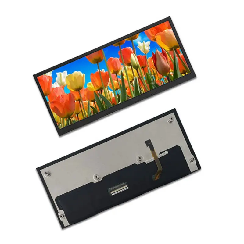
10.3 Inch Instrument Cluster LCD Module for Vehicle HMI
Model P/N
Size
Resolution
Brightness
Viewing Angle
Connector Type
Operating Temp
Overall(mm)
huisoar
HS103001S0
Brand
Panel Size (inch)
Model P/N
Resolution
Brightness (nits)
Viewing Angle
Contrast Ratio
Response Time
Overall (mm)
Active Area (mm)
Refresh Rate
Display Colors
Panel Type
Connector Type
Operating Temp
Touchscreen Type
Storage Temp
Work Mode
Pixel Format
Control Type
Operating Environment
Designed For
10.3 Inch Instrument Cluster LCD Module for Vehicle HMI
An ultra-wide 1280 × 480 IPS panel with 800 cd/m² luminance and a 30-pin LVDS interface for compact cockpit layouts.
Product Summary
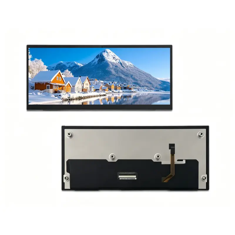
The Instrument Cluster LCD Module provides a long horizontal canvas for driving information, warning indicators, navigation prompts, equipment status, and other vehicle-HMI content. Its 1280 × 480 resolution supports segmented cockpit layouts without requiring the height of a conventional 16:9 display.
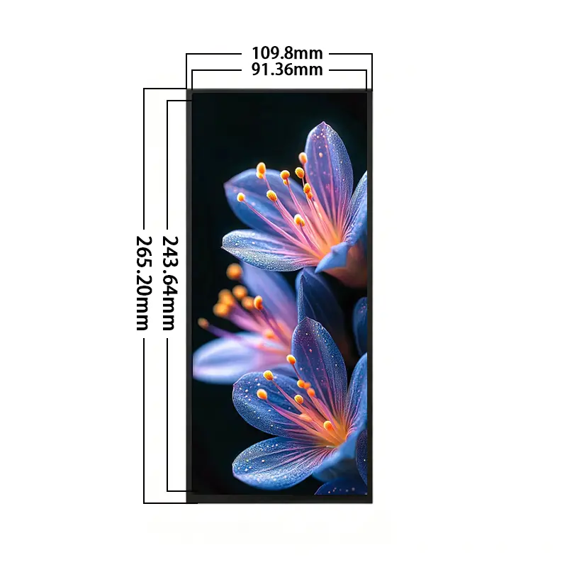
The 10.3-inch panel combines IPS viewing, 800 cd/m² typical luminance, a 30-pin LVDS interface, and a slim 265.2 × 109.8 × 6.0 mm structure. The standard configuration is non-touch, making it suitable for systems that use steering-wheel controls, physical switches, rotary inputs, remote commands, or a separately qualified touch layer.
Key Specifications
| Specification | Value |
|---|---|
| Display size | 10.3 inch |
| Resolution | 1280 × 480 pixels |
| Active area | 243.84 × 91.44 mm |
| Module outline | 265.2 × 109.8 × 6.0 mm |
| Panel technology | IPS a-Si TFT-LCD |
| Optical mode | Transmissive |
| Luminance | 800 cd/m² typical |
| Contrast ratio | 500:1 typical |
| Viewing angle | 80°/80°/80°/80°, L/R/U/D |
| Display colors | 65K/262K listed |
| Interface | LVDS, 30 pins |
| Backlight | WLED |
| Touch status | Non-touch |
| Operating temperature | −30°C to +70°C |
| Storage temperature | −30°C to +70°C |
1280 × 480 Instrument-Cluster Layout
Native Wide-Format UI Design
The 1280 × 480 raster is suited to horizontal information flow. A cluster interface can allocate separate zones for speed, system status, warning icons, navigation guidance, range information, operating mode, or equipment data.
The display should be driven at its native resolution whenever practical. Native operation preserves text proportions, line weight, icon clarity, and the intended relationship between horizontal and vertical UI elements.
Potential content zones include:
- Vehicle speed and operating state
- Warning and telltale icons
- Navigation directions
- Energy or fuel information
- Range and trip data
- Driver-assistance status
- Equipment alarms
- Machine operating parameters
The software layout should be designed specifically for 1280 × 480 rather than cropped from a conventional widescreen interface.
Active Area and Content Zones
The active image area is 243.84 × 91.44 mm. The front opening, decorative mask, safety margins, and visible content area should be planned separately from the 265.2 × 109.8 mm module outline.
Critical warnings and driving information should remain inside a validated safe area after bezel overlap, front-glass printing, and installation tolerances are applied.
IPS Optical Performance
800 cd/m² Visibility Boundary
The panel provides 800 cd/m² typical luminance. This supports higher-visibility cabin and equipment applications than a standard low-luminance indoor panel.
An 800 cd/m² panel does not by itself establish finished-system sunlight readability behind front glass.
Finished-screen visibility depends on:
- Front-glass transmission
- Surface reflection
- Decorative printing
- Air gap or bonding layer
- Installation angle
- Cabin geometry
- Direct and reflected ambient light
- Backlight dimming range
- Panel temperature
- Enclosure thermal design
The optical stack should therefore be evaluated under the expected installation lighting rather than approved from the panel luminance value alone.
Viewing Angle and Contrast
The IPS structure provides an 80° viewing specification in the left, right, upper, and lower directions. This supports off-axis viewing from different seating or operating positions.
The 500:1 typical contrast ratio provides separation for text, symbols, warnings, and graphical controls. Final perceived contrast will depend on ambient light, front-glass reflection, user-interface colors, and dimming control.
30-Pin LVDS Integration
Electrical Compatibility Checks
The module uses a 30-pin LVDS interface.
A 30-pin LVDS connector does not guarantee timing, voltage, channel, bit-depth, or pin compatibility with another panel.
Before connecting a host or controller board, verify:
- Native 1280 × 480 timing
- LVDS channel count
- Pixel or bit mapping
- Clock frequency
- Signal polarity
- Complete 30-pin assignment
- Connector pitch
- Contact side
- Pin-1 direction
- Logic supply rails
- Panel enable signals
- Backlight-driver requirements
- Dimming-control method
- Cable length and routing
The approved model-specific pinout and timing document should control electrical release.
Non-LVDS Hosts Require Conversion
HDMI, MIPI DSI, eDP, USB video, and parallel RGB are not interchangeable with LVDS. A bridge or controller board is required when the host does not provide the panel’s native LVDS signal and timing.
A conversion board must be evaluated for:
- Input video format
- Output LVDS mapping
- 1280 × 480 timing generation
- Panel power
- Backlight power
- Dimming behavior
- Start-up and shut-down behavior
- Connector and cable orientation
Mechanical Fit of the Instrument Cluster LCD Module
Enclosure and Bezel Planning
The module outline is 265.2 × 109.8 × 6.0 mm. The active area is 243.84 × 91.44 mm.
Mechanical design should confirm:
- Dashboard or equipment opening
- Active-area alignment
- Bezel overlap
- Decorative mask position
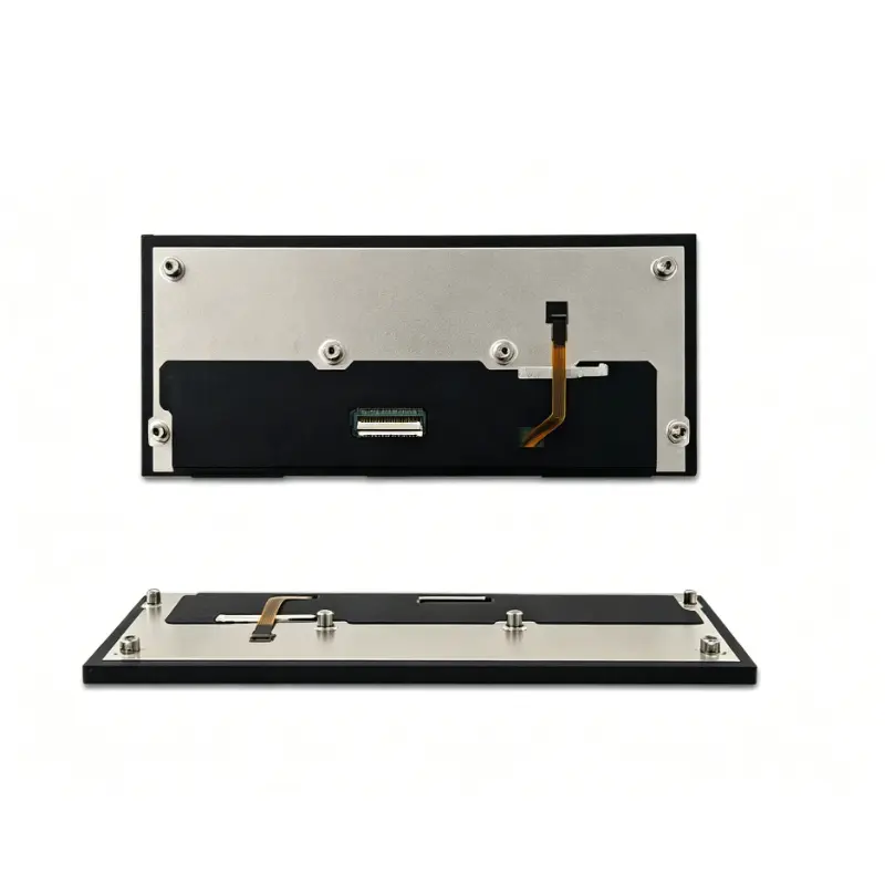
- Rear-component clearance
- Connector location
- Cable exit direction
- Cable bend radius
- Mounting pressure
- Front-glass stack
- Service-removal path
The approved mechanical drawing should be used before releasing tooling or enclosure parts.
Long-Panel Mounting Support
A long, narrow module can be more sensitive to twisting and uneven assembly force than a compact rectangular screen. Support should be distributed along the panel structure rather than concentrated at isolated points.
The design should avoid:
- Local frame pressure on the active area
- Excessive adhesive thickness variation
- Forced connector alignment
- Sharp cable folding
- Rear-component interference
- Housing distortion during fastening
Temperature and Qualification Boundaries
The display supports operation from −30°C to +70°C and storage from −30°C to +70°C.
These values do not independently establish:
- Automotive certification
- Continuous operation at the limit
- Vibration resistance
- Shock resistance
- Humidity resistance
- Condensation tolerance
- UV resistance
- EMC or ESD compliance
- Waterproofing
- Finished-cluster reliability
Qualification should use the final host, LVDS cable, power system, backlight driver, glass stack, enclosure, mounting structure, and software dimming behavior.
Application and Configuration Review
The Instrument Cluster LCD Module can be evaluated for:
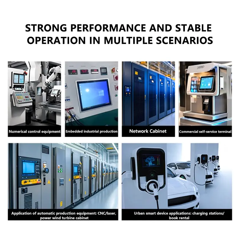
- Digital instrument clusters
- Vehicle navigation strips
- Cockpit information panels
- Transport-equipment HMIs
- Agricultural or construction-equipment indicators
- Narrow industrial status panels
- 3D-printer information displays
- Embedded diagnostic terminals
The module is not a finished display system. It does not automatically include a housing, HDMI board, power converter, operating system, touch panel, CAN interface, vehicle communication software, speakers, or application firmware.
Non-Touch Architecture
The standard module is non-touch. This is useful where the product uses:
- Steering-wheel controls
- Physical buttons
- Rotary encoders
- Remote commands
- Voice control
- A separate touch stack
- Another independently qualified input method
An optional touch solution requires its own cover dimensions, touch controller, interface, firmware, optical stack, and mechanical validation.
Configuration Scope
Project evaluation can cover:
- LVDS controller matching
- Complete 30-pin definition
- Custom LVDS cable
- Controller or bridge board
- Front glass
- Anti-glare or anti-reflective review
- Optical bonding
- Optional touch development
- Enclosure adaptation
- Mounting support
- Brightness review
- Branding and labeling
- Packaging
Custom configurations are generally reviewed from 500 pieces, subject to tooling requirements, material availability, and the requested specification. Sample and standard-module quantities are confirmed separately.
Procurement Checklist
Submit:
- Host processor or controller-board model
- Native 1280 × 480 timing
- LVDS channel count
- LVDS bit or pixel mapping
- Clock and polarity requirements
- Complete 30-pin assignment
- Connector pitch and orientation
- Panel supply requirements
- Backlight-driver output
- Dimming-control requirements
- Approved mechanical drawing
- Enclosure opening
- Front-glass specification
- Target finished-front luminance
- Input-method plan
- Operating environment
- Sample quantity
- Annual demand
- Production schedule
FAQ
About 10.3 Inch Instrument Cluster LCD Module
What must be checked before connecting another 30-pin LVDS controller?
How should a 1280 × 480 cluster interface be prepared?
Is 800 cd/m² sufficient behind automotive front glass?
Which dimensions should control enclosure release?
When should the non-touch version be selected?
Freya Yang
+86 18318948097