Freya Yang
+86 18318948097
+852 62667476
11.6 Inch Full View TFT Module Capacitive Touch Screen for Embedded Control Panels
Model P/N
Size
Resolution
Brightness
Viewing Angle
Connector Type
Operating Temp
Overall(mm)
huisoar
HS116EB5S + MTP
Brand
Panel Size (inch)
Model P/N
Resolution
Brightness (nits)
Viewing Angle
Contrast Ratio
Response Time
Overall (mm)
Active Area (mm)
Refresh Rate
Bezel Opening
Display Colors
Panel Type
Connector Type
Surface Treatment
Operating Temp
Touchscreen Type
Storage Temp
Work Mode
Pixel Format
Control Type
Weight (g)
Protective Glass Specification
Operating Environment
Designed For
11.6 Inch Full View TFT Module for Embedded Control Panels
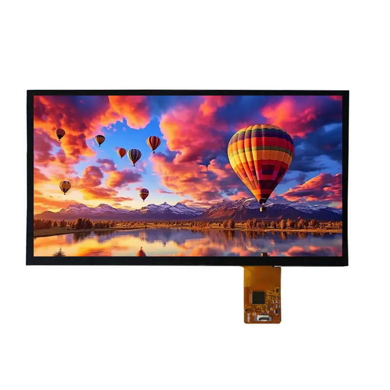
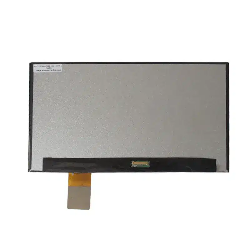
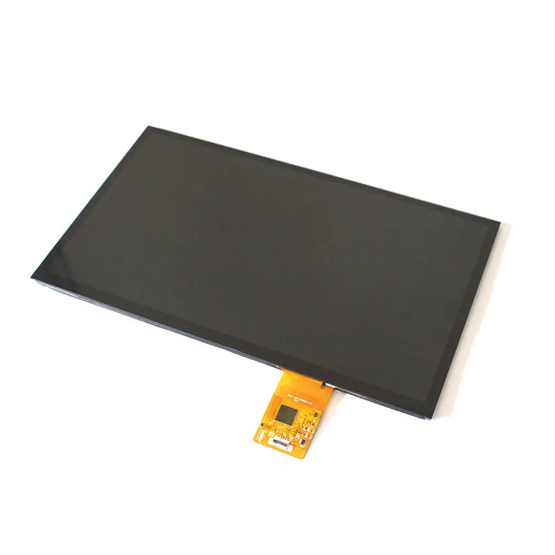
The 11.6 Inch Full View TFT Module provides a 1920 × 1080 image area, full-viewing optical behavior and a capacitive-touch assembly for compact embedded control interfaces. Its confirmed LCD geometry includes a 256.32 × 144.18 mm active area and a 267.7 × 164.4 × 5.7 mm panel outline.
The assembly should be integrated as three related but separate subsystems: the TFT image path, the LED backlight and the capacitive-touch control path. Connector count, product-title wording or physical cable fit alone cannot establish electrical compatibility.
Product Summary
This 11.6-inch module is designed for equipment that needs Full HD information density within a relatively compact mechanical envelope. The transmissive, normally black TFT structure and full-viewing characteristic support operator screens, status pages, equipment graphics and touch-based controls.
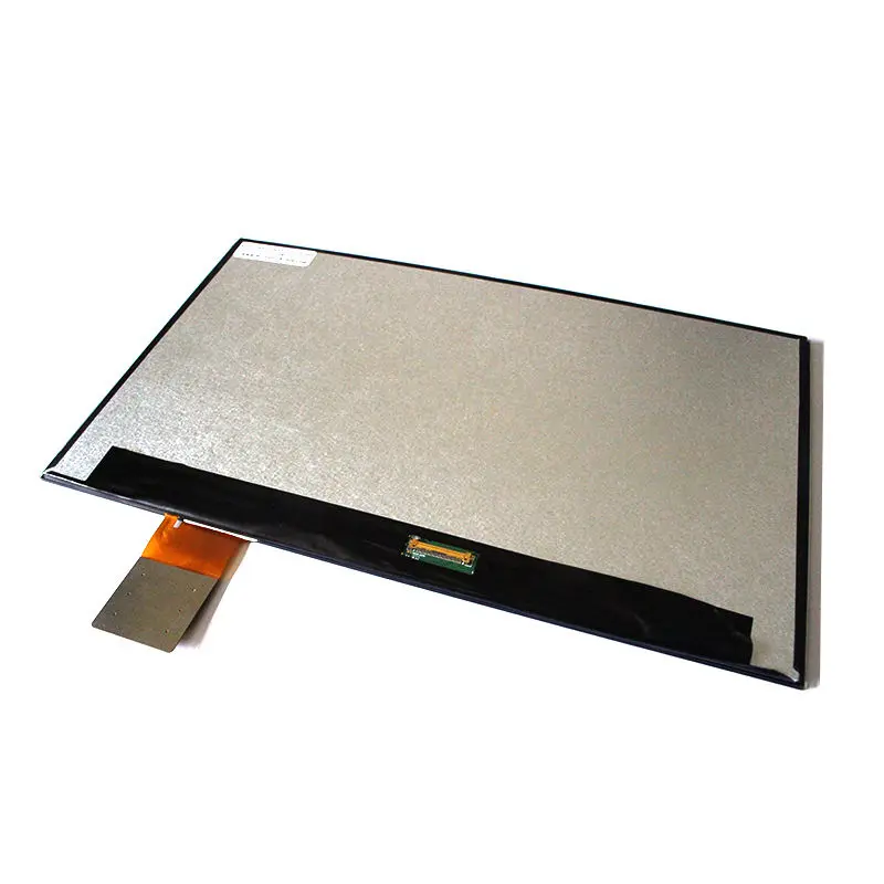
The LCD specification identifies a 30-pin FPC, while the commercial title mentions 60 pins. The structured specification and drawing support the 30-pin LCD connection, so the 60-pin description should not be used for controller or cable selection without a complete assembly pinout.
The standard luminance reference is 250 cd/m² typical. This positions the module for indoor or controlled-light systems, not direct-sunlight installations.
Key Specifications at a Glance
The panel provides 1920 × 1080 pixels in an RGB vertical-stripe arrangement. The active area measures 256.32 × 144.18 mm, while the LCD body measures 267.7 × 164.4 × 5.7 mm.
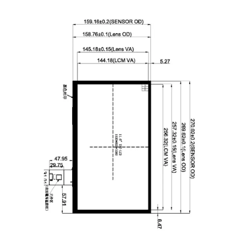
The touch drawing identifies larger and separate external boundaries, including a 270.02 ± 0.2 × 159.16 ± 0.2 mm sensor outline and a 268.56 ± 0.1 × 158.76 ± 0.1 mm lens outline. These dimensions must not be substituted for the LCD outline or combined into a single ambiguous module size.
Full HD Image Area for Control Interfaces
1920 × 1080 Information Density
Full HD resolution allows compact control equipment to present detailed menus, trend views, diagnostics, status indicators and contextual controls without excessive page switching. Fine text and icons can be displayed more clearly than on lower-resolution panels of the same diagonal size, provided the interface is designed for the expected viewing distance.
The host must output a compatible native timing and eDP link. Resolution equality alone does not establish electrical compatibility with another Full HD panel.
Full-Viewing Normally Black Operation
The display is described as full viewing, transmissive and normally black. This makes it suitable for operator interfaces that may be viewed from several normal working positions rather than only from a centered line of sight.
No directional angle values are assigned because the supplied information does not confirm a left/right/up/down order or numeric viewing-angle sequence. Full-viewing performance should still be evaluated behind the intended lens and at the final mounting angle.
The surface treatment is glare. Reflections from overhead lighting, a front cover, an air gap or protective lens should be assessed on the completed assembly.
eDP and Connector Qualification
Why the 30-Pin and 60-Pin Conflict Matters
The detailed product attributes identify a 30-pin FPC, and the drawing presents a 30-position LCD pin table. The marketplace title, however, says 60 pins.
The confirmed 30-pin information should be used only as a starting point. Procurement and engineering teams should request the full LCD and touch pin definitions before releasing a cable, adapter board or host PCB.
A matching connector count does not prove that an eDP host and LCD module are compatible.
Compatibility review should include lane count, link rate, AUX routing, power rails, enable signals, backlight controls, connector pitch, contact side and FPC orientation. Comparable eDP panels can share the same physical connector while differing in one or more of these parameters.
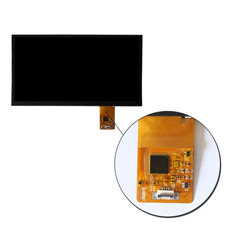
Separate LCD and Touch Signal Paths
The eDP connection describes the image path. It does not automatically describe the capacitive-touch communication path.
The table entry ILI2511 is more plausibly associated with the touch subsystem than with the eDP video interface, but its exact role must be confirmed in the approved touch specification. Comparable touch assemblies may use I²C or USB, yet neither interface should be assumed for this model.
The LCD video link and capacitive-touch control path require separate electrical qualification.
Mechanical Integration of the 11.6 Inch Full View TFT Module
LCD Active Area and Outline
The visible active area is 256.32 × 144.18 mm. The LCD outline is 267.7 × 164.4 × 5.7 mm.
These dimensions should guide the LCD support structure, internal clearance and bezel relationship. The enclosure must avoid concentrated pressure on the active glass, border, FPC exit and bonded touch region.
A separate marketplace dimension of 263.4 × 157.22 × 2.8 mm conflicts with the detailed LCD outline. It should not control production tooling unless it is tied to a clearly identified subassembly in an approved drawing.
Sensor, Lens and Viewing-Area Boundaries
The touch drawing distinguishes the following boundaries:
- sensor outline;
- lens outline;
- lens viewing area;
- LCM viewing area;
- LCM active area.
This distinction matters because the touch sensor or lens can define the largest required opening or enclosure clearance even when the LCD body is smaller.
The final enclosure should be released only against one approved combined drawing that identifies all tolerances, adhesive or air-gap structure, FPC routing and connector access.
Indoor Luminance and Environmental Limits
The standard display luminance is 250 cd/m² typical. This can be appropriate for indoor control panels, equipment consoles and workstations where ambient light is managed.
The 250 cd/m² typical panel is intended primarily for indoor or controlled-light equipment.
A front lens, glare surface, air gap, printing, tint or additional protective layer can change apparent brightness and reflection behavior. The finished stack should therefore be tested in the intended lighting rather than assessed only from the bare LCD.
The confirmed operating-temperature range is 0°C to +50°C. Storage is specified from −10°C to +60°C. Systems requiring operation beyond those limits need another qualified module or a separately validated configuration.
Recommended Application Routes
The display may be evaluated for:
- embedded control panels;
- compact operator consoles;
- test and service equipment;
- smart terminals;
- indoor automation interfaces;
- equipment configuration and diagnostic panels.
These are integration routes, not certification claims. Suitability depends on the host interface, touch-controller definition, optical environment, enclosure design and required operating conditions.
The module should not be presented as automotive grade, medical certified, waterproof, outdoor readable or safety qualified without product-specific documentation.
Customization and Sample Approval
Project-specific review may cover:
- touch-controller and communication interface;
- cover-lens geometry and printing;
- sensor and FPC routing;
- LCD connector definition;
- cable orientation;
- brightness target;
- mechanical adaptation;
- packaging;
- controller-board matching.
The standard product MOQ and customization MOQ should be treated separately. Standard quantities and sample availability are confirmed according to the selected module configuration. Logo, packaging or graphic customization may require materially higher quantities than a standard-module order.
Before production approval, a representative display and touch assembly should be tested for image stability, touch communication, cable alignment, backlight behavior, enclosure fit and operation across the required temperature range.
Procurement Checklist
Submit the following before controller or enclosure release:
- native 1920 × 1080 timing;
- expected eDP lane count and link rate;
- complete LCD and host pin assignments;
- connector pitch, contact side and FPC orientation;
- panel and backlight voltage requirements;
- touch-controller part number and communication interface;
- touch connector and pinout;
- LCD, sensor, lens and viewing-area drawings;
- cover-lens and optical-stack construction;
- target ambient-light conditions;
- operating and storage temperature requirements;
- sample quantity;
- annual demand;
- production and validation schedule.
FAQ
About 11.6 Inch Full View TFT Module
Can this module replace another 11.6-inch 1920 × 1080 eDP panel?
What information is required to integrate the capacitive-touch function?
Which dimensions should be used for the front-panel opening?
Is 250 cd/m² adequate behind a protective lens?
Freya Yang
+86 18318948097