Freya Yang
+86 18318948097
+852 62667476
12.1 Inch 1024×768 Capacitive Touch Display Module for 4:3 HMI Panels
Model P/N
Size
Resolution
Brightness
Viewing Angle
Connector Type
Operating Temp
Overall(mm)
huisoar
HS012101LZR20B
Brand
Panel Size (inch)
Model P/N
Resolution
Brightness (nits)
Viewing Angle
Contrast Ratio
Response Time
Overall (mm)
Active Area (mm)
Refresh Rate
Bezel Opening
Display Colors
Panel Type
Connector Type
Operating Temp
Touchscreen Type
Storage Temp
Work Mode
Operating Environment
I/O Interface
Designed For
12.1 Inch 1024x768 Capacitive Touch Display Module for 4:3 HMI Panels
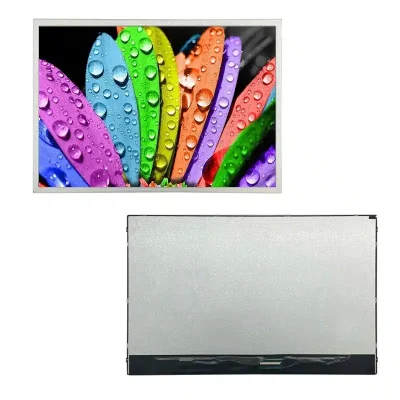
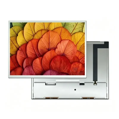
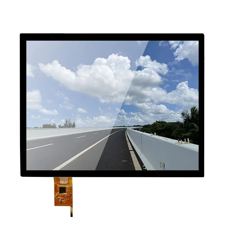
A 12.1-inch XGA display is a practical format for operator interfaces that still use a 4:3 workspace. This 12.1 Inch 1024x768 Capacitive Touch Display Module for 4:3 HMI combines 1024 × 768 resolution, 600 cd/m² luminance, a 20-pin LVDS display interface, a 245.76 × 184.32 mm active area, and a listed −30°C to +85°C temperature range. A projected-capacitive touch configuration is available, but the ordered touch stack and touch-controller interface should be confirmed for the production revision.
Product Summary
Native XGA Geometry for 4:3 HMI Layouts
The native 1024 × 768 raster preserves the 4:3 geometry used by established industrial menus, process screens, equipment dashboards, and diagnostic interfaces. Native operation avoids unnecessary scaling of text, buttons, trend charts, and legacy UI assets.
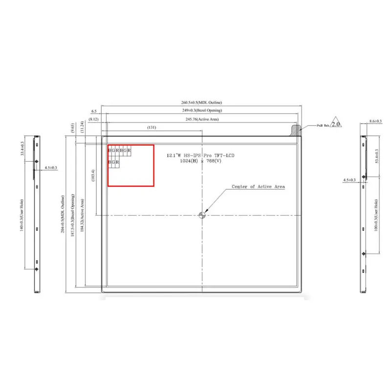
The mechanical drawing identifies a 245.76 × 184.32 mm active area, 249.0 × 187.5 mm bezel opening, and approximately 260.5 × 204.0 × 8.6 mm module envelope.
600 cd/m² for High-Ambient Equipment
The panel is specified at 600 cd/m². That output can support bright indoor or sheltered equipment, but the finished product still needs optical validation with the selected cover glass, touch stack, bonding method, reflections, and installation lighting.
A 600 cd/m² panel rating does not by itself establish finished-system sunlight readability.
Key Specifications
| Parameter | Specification |
|---|---|
| Display size | 12.1 inches |
| Resolution | 1024 × 768 pixels, XGA |
| Aspect ratio | 4:3 |
| Active area | 245.76 × 184.32 mm |
| Module outline | 260.5 × 204.0 × 8.6 mm drawing value |
| Bezel opening | 249.0 × 187.5 mm |
| Brightness | 600 cd/m² |
| Viewing | All/free viewing designation |
| Display mode | Transmissive, normally black |
| LCD interface | LVDS, 20 pins |
| Listed LED life | 50,000 hours under the stated reference conditions |
| Operating temperature | −30°C to +85°C |
| Storage temperature | −30°C to +85°C |
| Touch | Projected-capacitive configuration; ordered stack/interface to confirm |
| External board route | Conversion-board option; inclusion and I/O to confirm |
LVDS Integration for the 1024 × 768 Display Path
Confirm the Complete 20-Pin Definition
The 20-pin LVDS connector identifies the display signal family and connector count, not complete host compatibility. Before controller release, compare native XGA timing, full pin assignment, channel and bit mapping, connector orientation, cable construction, panel voltage requirements, and backlight electrical requirements.
A matching 20-pin LVDS connector does not guarantee timing, voltage, mapping, or pin compatibility.
Keep Conversion-Board Functions Separate
A conversion-board route is available when a system does not drive the panel directly from native LVDS. Any HDMI or other external video input belongs to that separate controller-board architecture, not to the LCD panel itself. Board model, firmware, cables, input connectors, power requirements, and order inclusion should be defined separately.
12.1 Inch 1024x768 Capacitive Touch Display Module for 4:3 HMI
Capacitive Touch Requires Its Own Interface Definition
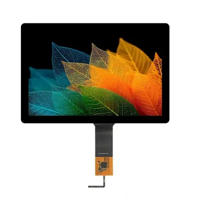
Projected-capacitive touch is an order-specific configuration. Confirm whether the ordered assembly includes the touch sensor, cover lens, bonding layer, touch controller, and cable.
The 20-pin LVDS specification applies to the LCD image path; the capacitive-touch controller interface is not identified and must be confirmed separately.
Touch Stack Changes Mechanical and Optical Fit
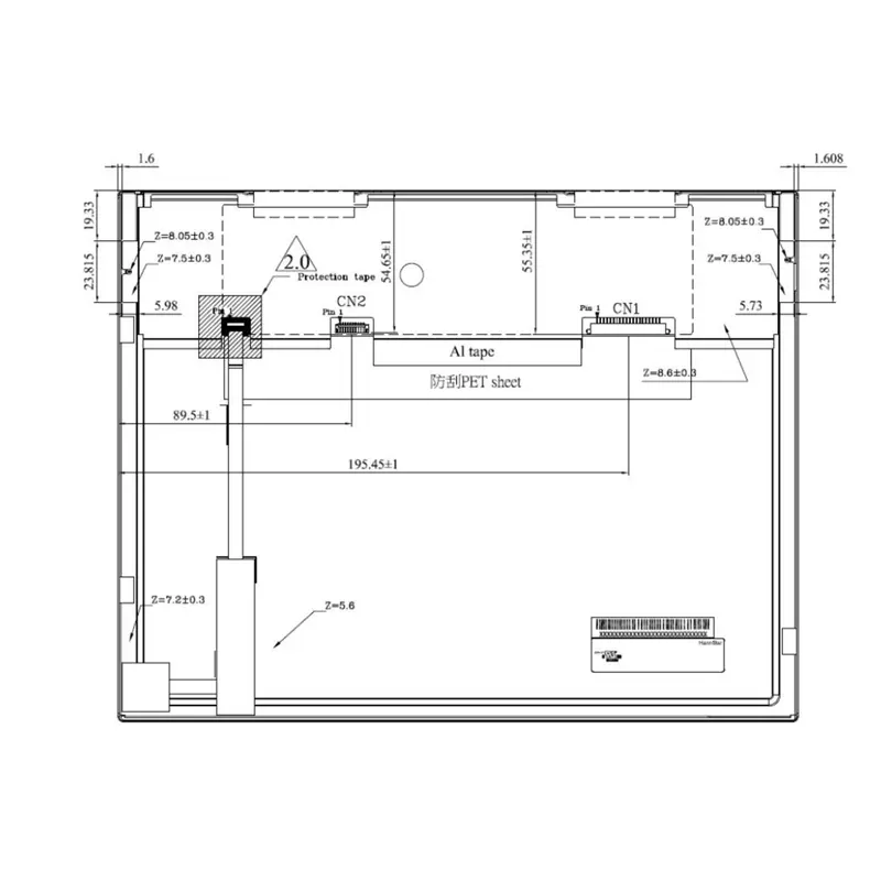
A capacitive-touch assembly can change overall thickness, front-window geometry, optical transmission, reflections, FPC routing, and enclosure clearances. When touch is ordered, mechanical approval should use the combined LCD-plus-touch drawing rather than the bare-panel outline alone.
Wide-Temperature Qualification
Use the −30°C to +85°C Range as a Component Boundary
Operating and storage temperature are both specified from −30°C to +85°C. The module range does not automatically qualify the complete HMI enclosure, touch stack, controller board, adhesives, cables, or power system for the same conditions.
The −30°C to +85°C module range does not establish the environmental rating of the finished equipment.
Lock the Panel-Mode Revision Before Optical Approval
Before optical approval, lock the ordered panel mode to the production specification because the technology designation requires revision confirmation. Integration planning can rely on the confirmed 1024 × 768 resolution, all/free viewing designation, transmissive normally-black mode, dimensions, luminance, LVDS interface, and temperature range.
Mechanical Planning for 4:3 HMI Panels
The drawing identifies 245.76 × 184.32 mm active area, 249.0 × 187.5 mm bezel opening, and approximately 260.5 × 204.0 × 8.6 mm module size. Use the approved production drawing to control tooling tolerances.
For replacement work, compare active area, outline, bezel opening, mounting features, connector location, flex orientation, cable bend space, and touch-stack depth. Matching 12.1-inch size and 1024 × 768 resolution does not guarantee a drop-in replacement.
Application Direction
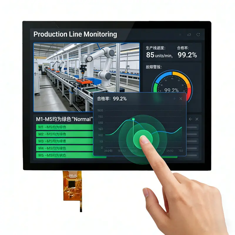
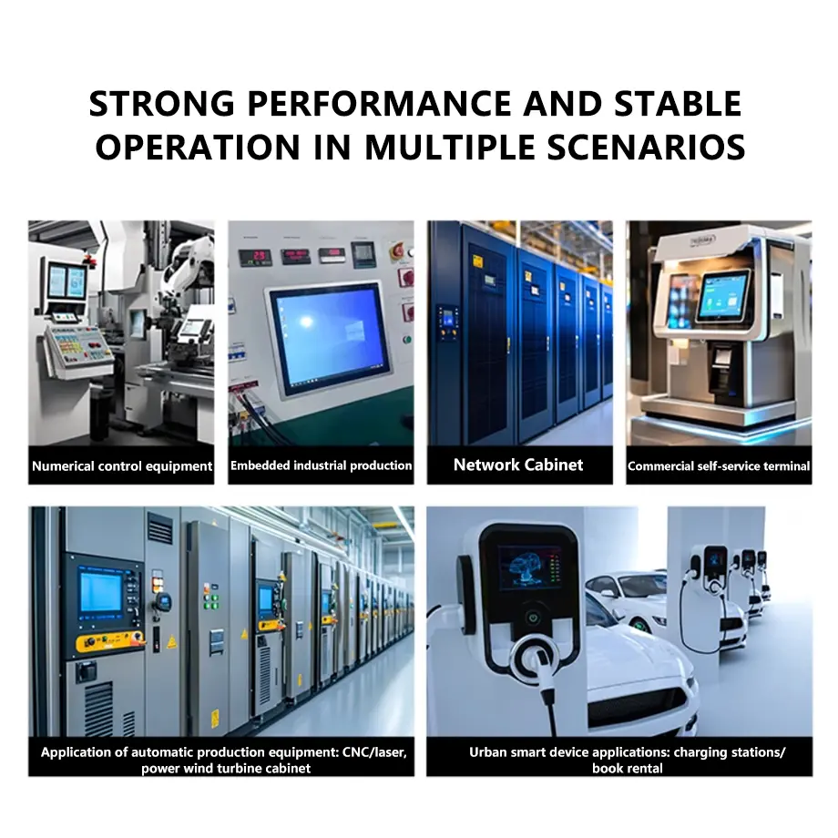
The 12.1 Inch 1024x768 Capacitive Touch Display Module for 4:3 HMI fits industrial HMI panels, embedded operator interfaces, control terminals, test and service equipment, smart-home control panels, and other professional 4:3 interfaces that need XGA graphics and a touch-enabled front end.
Medical-equipment interfaces may be evaluated where the finished device completes its own safety, EMC, cleaning, usability, and regulatory qualification. The display module itself should not be presented as medical certified without product-specific evidence.
Customization and Project Review
Project review can cover capacitive-touch stack definition, cover lens, bonding, brightness target, backlight configuration, pin definition, LVDS cable, conversion-board selection, mechanical adaptation, branding, and packaging.
Custom configurations are generally reviewed from 500 pieces, subject to tooling requirements, material availability, and the requested specification. Sample and standard-module quantities are confirmed separately.
Procurement Checklist
Before sample approval, confirm the production revision, native 1024 × 768 timing, complete 20-pin LVDS assignment, connector orientation, panel and backlight electrical requirements, 600 cd/m² luminance tolerance, and approved mechanical drawing.
Also confirm the 245.76 × 184.32 mm active area, 249.0 × 187.5 mm bezel opening, all-view designation, final panel-mode label, 50,000-hour LED-life reference conditions, −30°C to +85°C operating/storage limits, capacitive-touch stack and controller interface, conversion-board requirement, sample quantity, annual demand, and validation criteria.
FAQ
About 12.1 Inch 1024x768 Capacitive Touch Display Module
What must be checked before connecting a 20-pin LVDS controller?
Which touch-interface details are required before host-board design?
Is 600 cd/m² sufficient behind a cover lens?
Which mechanical dimensions should control enclosure tooling?
When should a conversion board be specified?
Freya Yang
+86 18318948097