Freya Yang
+86 18318948097
+852 62667476
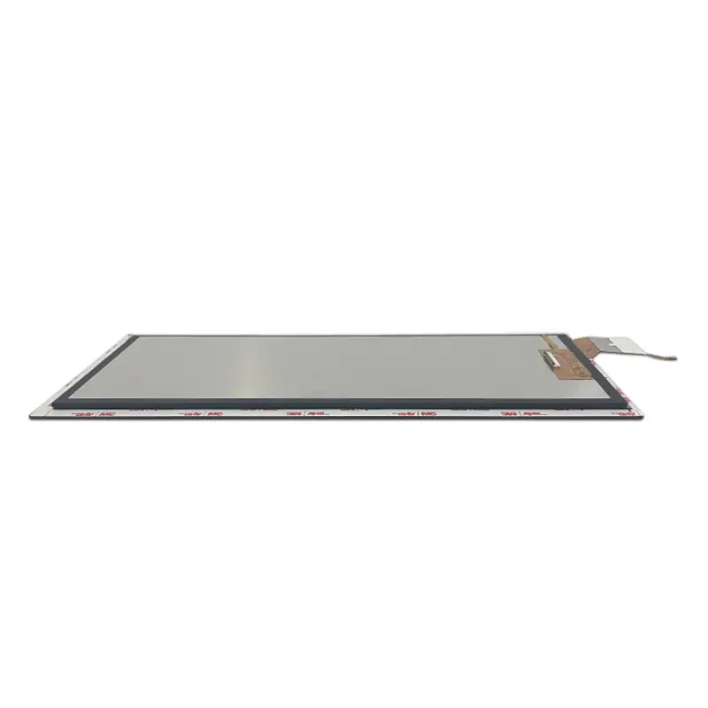
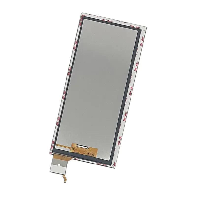
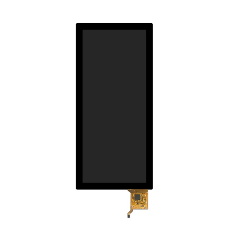
12.3 Inch Vehicle Portrait Touchscreen Module for Navigation HMI
Model P/N
Size
Resolution
Brightness
Viewing Angle
Connector Type
Operating Temp
Overall(mm)
huisoar
HS123006S0-KK
Brand
Panel Size (inch)
Model P/N
Resolution
Brightness (nits)
Viewing Angle
Contrast Ratio
Response Time
Overall (mm)
Active Area (mm)
Refresh Rate
Display Colors
Panel Type
Connector Type
Operating Temp
Touchscreen Type
Storage Temp
Work Mode
Pixel Format
Touch Interface
Control Type
Protective Glass Specification
Operating Environment
I/O Interface
Designed For
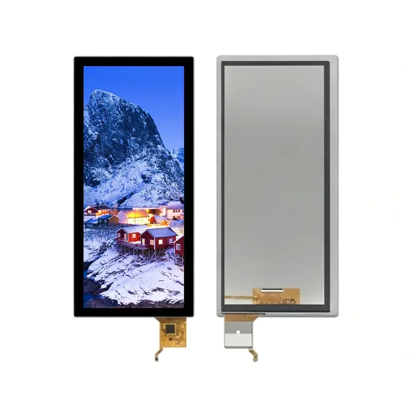
12.3 Inch Vehicle Portrait Touchscreen Module for Navigation HMI
A slim 720 × 1920 IPS touch module with 40-pin MIPI display input and G+G I²C touch for vehicle and machinery interfaces.
Product Summary
The Vehicle Portrait Touchscreen Module provides a tall interface canvas for navigation, machine guidance, instrument data and vertically organized control menus. Its native 720 × 1920 resolution supports maps, alerts, operating parameters and command zones in equipment where a conventional landscape display would use front-panel space inefficiently.
The 12.3-inch module combines IPS viewing, 600 cd/m² typical luminance, a 40-pin MIPI display connection and G+G projected capacitive touch. The touch system uses a separate I²C communication path, allowing the display and touch functions to be qualified independently during controller-board development.
Key Specifications
| Specification | Value |
|---|---|
| Display size | 12.3 inch |
| Resolution | 720 × 1920 pixels |
| Aspect ratio | 3:8 |
| Active area | 109.51 × 292.03 mm |
| Outline | 134.11 × 316.63 × 4.7 mm |
| Panel type | IPS a-Si TFT LCD |
| Luminance | 600 cd/m² typical |
| Viewing angle | 80°/80°/80°/80°, L/R/U/D |
| Display colors | 16.7 million |
| Display interface | MIPI, 40 pins |
| Display IC identifier | ILI79600A-XA |
| Touch type | G+G projected capacitive |
| Touch interface | I²C |
| Touch-controller identifier | ILI2511 |
| Backlight | WLED |
| Operating temperature | −20°C to +70°C |
| Storage temperature | −30°C to +80°C |
Portrait 720 × 1920 Interface Layout
Navigation and Machine-Status Composition
The 3:8 screen format supports top-to-bottom information flow. A navigation layout can place route guidance, machine position, warnings, operational values and touch controls in separate vertical zones without compressing them into a shallow horizontal strip.
This format is especially relevant for:
- Agricultural guidance terminals
- Engineering-vehicle navigation
- Vehicle control consoles
- Instrument and status displays
- Industrial process interfaces
- Vertical smart-equipment panels
The UI should define text size, control spacing, safe touch targets and alert priority for the intended viewing distance and mounting position.
Native Raster and Active Area
The display should be driven at its native 720 × 1920 resolution whenever practical. Scaling a conventional landscape interface into the portrait raster can distort icons, reduce text clarity and waste the available vertical space.
The active image area is 109.51 × 292.03 mm. This should be distinguished from the 134.11 × 316.63 mm module outline when defining the visible window, decorative mask and touchable region.
Optical and Touch Performance
600 cd/m² Lighting Boundary
The panel provides 600 cd/m² typical luminance. This can support vehicle cabins, equipment consoles and controlled industrial environments with moderate or elevated ambient lighting.
A 600 cd/m² panel does not by itself establish finished-system sunlight readability behind cover glass.
The completed optical stack should be evaluated for:
- Cover-glass transmission
- Surface reflections
- Decorative printing
- Air gap or optical bonding
- Mounting angle
- Direct and indirect daylight
- Night-time dimming
- Backlight heating
- Enclosure temperature
G+G Projected Capacitive Touch
The touch structure uses two glass layers and projected capacitive sensing. This supports a rigid front stack suitable for direct control interfaces, but the exact cover thickness, hardness, touch-point count and supported glove or wet-touch behavior are not defined.
Touch validation should include:
- Cover-glass construction
- Sensor-to-display alignment
- Touch-point requirement
- Edge accuracy
- Noise immunity
- Grounding
- I²C routing
- Reset and interrupt handling
- Firmware configuration
- Calibration
- Final enclosure testing
MIPI Display and I²C Touch Integration
40-Pin MIPI Host Qualification
The display uses a 40-pin MIPI connection.
A 40-pin MIPI connector does not guarantee lane, timing, voltage, initialization or pin compatibility with another panel.
Before connecting the host, verify:
- MIPI DSI lane count
- Video or command mode
- Native 720 × 1920 timing
- Link frequency
- Pixel format
- Complete 40-pin assignment
- Connector pitch
- Contact side
- Pin-1 orientation
- Panel-voltage rails
- Enable and reset signals
- Approved initialization data
The ILI79600A-XA identifier does not independently prove that a generic initialization sequence will operate the module.
Separate ILI2511 Touch-Control Path
The MIPI display path and ILI2511-controlled I²C touch path are separate interfaces.
The touch system requires its own electrical review, including:
- I²C address
- Logic voltage
- Reset pin
- Interrupt pin
- Pull-up arrangement
- Firmware or configuration package
- Touch-point support
- Coordinate orientation
- Display-to-touch rotation
- ESD and noise behavior
A working display image does not confirm that the touch interface is correctly routed or configured.
Mechanical Integration of the Vehicle Portrait Touchscreen Module
Slim Outline and Enclosure Fit
The overall module measures 134.11 × 316.63 × 4.7 mm. The long portrait structure requires support that controls bending and keeps pressure away from the active display and touch sensor.
Mechanical design should confirm:
- Front opening
- Active-area margin
- Touchable region
- FPC exit location
- Cable bend radius
- Connector keep-out
- Rear clearance
- Mounting support
- Gasket or adhesive position
- Service-removal path
The approved dimensional drawing should control tooling release.
Cover Stack and FPC Clearance
The published thickness covers the module assembly, but the final product may add adhesive, protective glass, bezel material or optical bonding.
The total stack should therefore account for:
- Module thickness
- Cover-glass thickness
- Bonding material
- Decorative mask
- FPC bend
- Connector height
- Rear support
- Enclosure tolerance
FPC routing should avoid sharp bends and contact with moving or high-temperature components.
Temperature and Qualification Boundaries
The module is specified for operation from −20°C to +70°C and storage from −30°C to +80°C.
These temperature ranges do not independently establish:
- Automotive qualification
- Medical certification
- Vibration resistance
- Humidity resistance
- EMC or ESD compliance
- UV stability
- Waterproofing
- Continuous operation at the maximum temperature
- Finished-system reliability
Qualification should use the final controller, cable, touch firmware, cover stack, backlight drive, enclosure and mounting arrangement.
Application and Configuration Review
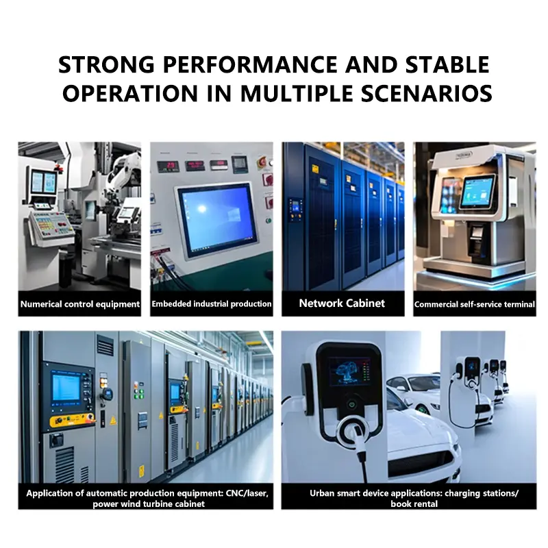
The module can be evaluated for:
- Agricultural-machine navigation
- Engineering-vehicle guidance
- Vehicle instrument interfaces
- Center-control displays
- Industrial HMI panels
- Vertical machine-status terminals
- Smart equipment controls
- Portable navigation equipment
The module is not a complete navigation terminal. GPS, CAN communication, operating software, audio, wireless connectivity, enclosure protection and finished-system power conversion require additional hardware.
Configuration Scope
Project review may cover:
- MIPI host and cable matching
- Complete 40-pin definition
- Display initialization package
- ILI2511 I²C touch integration
- Cover glass
- Anti-glare or anti-reflective treatment
- Optical bonding
- Enclosure adaptation
- FPC routing
- Brightness validation
- Branding and labeling
- Controller-board matching
Custom configurations are generally reviewed from 500 pieces, subject to tooling requirements, material availability and the requested specification. Sample and standard-module quantities are confirmed separately.
Procurement Checklist
Submit:
- Host processor or controller-board model
- Native 720 × 1920 timing
- MIPI DSI lane count
- Video or command mode
- Link frequency
- Pixel format
- Complete 40-pin assignment
- Connector pitch and orientation
- Panel-voltage rails
- Approved ILI79600A-XA initialization package
- ILI2511 I²C address and logic voltage
- Touch reset and interrupt routing
- Required touch-point count
- Enclosure and cover-glass drawings
- Optical-bonding requirement
- Target finished-front luminance
- Operating environment
- Sample quantity
- Annual demand
FAQ
About 12.3 Inch Vehicle Portrait Touchscreen Module
What must be checked before connecting the module to a 40-pin MIPI host?
How should a 720 × 1920 interface be prepared?
How are the display and touch interfaces separated?
Is 600 cd/m² sufficient behind a cover lens?
Which values control enclosure and environmental qualification?
Freya Yang
+86 18318948097