
Freya Yang
+86 18318948097
+852 62667476
14 Inch 16:10 TFT Display Panel for Embedded Controls
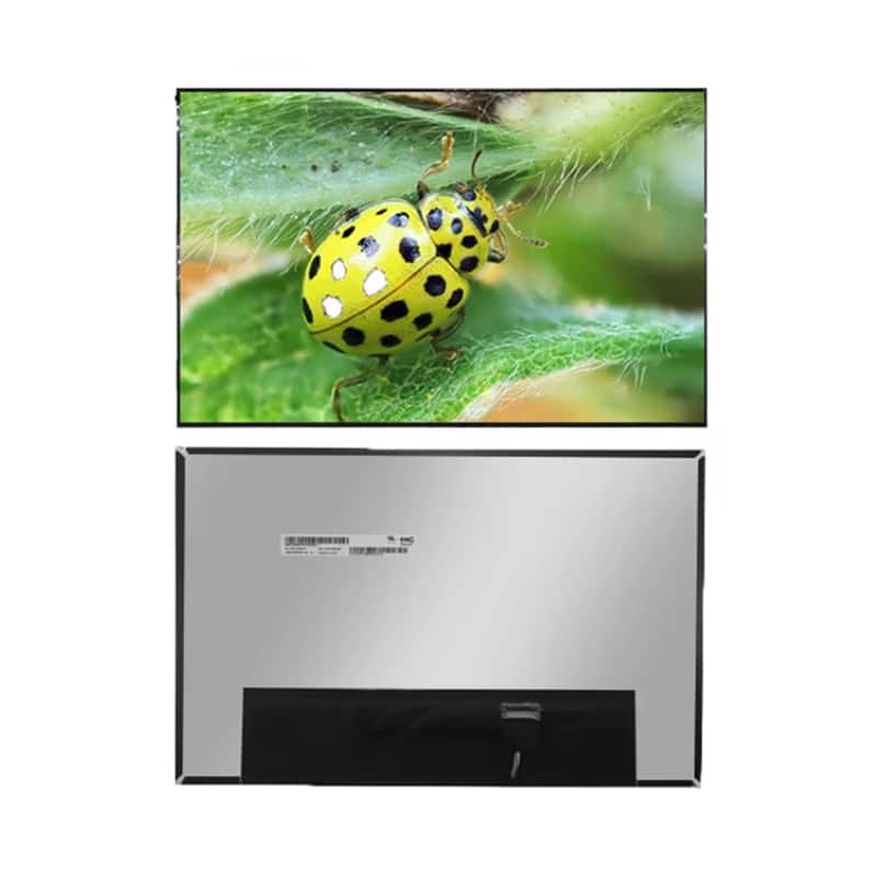

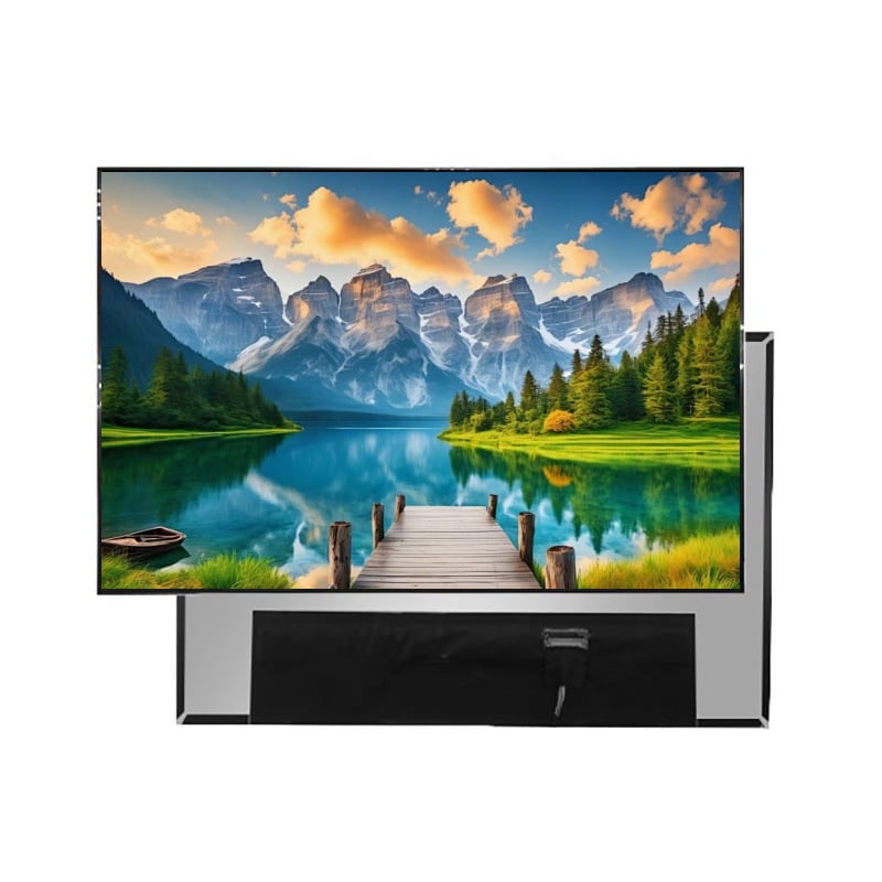



Model P/N
Size
Resolution
Brightness
Viewing Angle
Connector Type
Operating Temp
Overall(mm)
huisoar
HS140FHM-300-30
Brand
Panel Size (inch)
Model P/N
Resolution
Brightness (nits)
Viewing Angle
Contrast Ratio
Response Time
Overall (mm)
Active Area (mm)
Refresh Rate
Display Colors
Panel Type
Connector Type
Surface Treatment
Operating Temp
Touchscreen Type
Storage Temp
Work Mode
Pixel Format
Input Voltage (V)
Control Type
Operating Environment
Motherboard Type
Designed For
14 Inch 16:10 TFT Display Panel for Embedded Controls
A slim 1920 × 1200 IPS panel with eDP connectivity and anti-glare treatment for compact control and diagnostic equipment.
Product Summary
The 14 Inch 16:10 TFT Display Panel provides a WUXGA workspace for embedded controls, industrial terminals, diagnostic equipment, and compact systems that need more vertical image area than a conventional 16:9 panel. Its native 1920 × 1200 resolution supports detailed text, operating data, menus, waveforms, status regions, and multi-panel user interfaces.
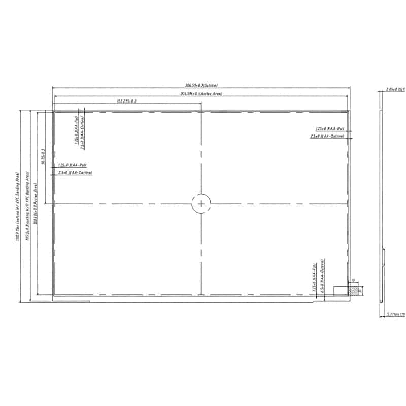
The display combines IPS image performance, 345 cd/m² luminance, RGB vertical-stripe pixels, an anti-glare surface with 25% haze, and an eDP display connection. Its panel-only mechanical reference is 306.59 × 197.50 × 3.00 mm maximum, subject to the exact PCBA, FPC, and supplied-assembly configuration.
Key Specifications
| Specification | Value |
|---|---|
| Display size | 14.0 inch |
| Resolution | 1920 × 1200 pixels, WUXGA |
| Aspect ratio | 16:10 |
| Panel technology | IPS TFT LCD |
| Active area | 301.594 × 188.496 mm |
| Pixel pitch | 0.1571 × 0.1571 mm |
| Pixel arrangement | RGB vertical stripe |
| Luminance | 345 cd/m² |
| Display colors | 16.7 million colors |
| Color gamut | NTSC 45% typical |
| Surface treatment | Anti-glare, 25% haze |
| Surface hardness | 3H |
| Response time | 25 ms |
| Selected interface | eDP |
| Panel outline | 306.59 ± 0.3 × 197.50 ± 0.3 mm |
| Panel-only depth | 3.00 mm maximum without PCBA/FPC |
| Operating temperature | −20°C to +70°C |
| Storage temperature | −30°C to +80°C |
| Standard touch status | Non-touch configuration |
WUXGA Workspace for Embedded Interfaces
Extra Vertical Space in a 16:10 Layout
The 1920 × 1200 pixel matrix provides 120 additional vertical pixels compared with a 1920 × 1080 panel. That additional workspace can accommodate persistent toolbars, status regions, navigation areas, diagnostic data, parameter lists, or waveform controls without compressing the primary content area.
A 16:10 interface can be useful for equipment software that balances detailed working content with permanent operating controls. It can also reduce the need for pop-up layers or frequent page switching in compact HMI and test-equipment applications.
The system UI should still be evaluated at the intended viewing distance. Pixel density, text size, scaling, touch-target dimensions, and operator workflow affect usability independently of resolution.
Pixel Pitch and Active-Area Planning
The active image area measures 301.594 × 188.496 mm, with a pixel pitch of 0.1571 × 0.1571 mm.
The active area defines the visible image region and must not be confused with the complete 306.59 × 197.50 mm panel outline. Front-window and bezel drawings should preserve the full image area while accommodating panel borders, manufacturing tolerances, adhesive overlap, and any protective front stack.
eDP Host Integration
Link, Timing, and Pin Compatibility
The selected configuration uses an eDP display interface. eDP transports video from an embedded graphics source to an internal display panel and supports scalable link configurations, but the interface name alone does not define the specific panel implementation.
Before connecting a host, confirm:
- Native 1920 × 1200 timing
- eDP lane count
- Link rate
- Connector series and pitch
- Contact orientation
- Complete pin assignment
- Panel power rails
- AUX-channel implementation
- Hot-plug or panel-detection requirements
- Reset or enable signals
- Backlight enable and brightness control
A matching eDP connector does not guarantee panel timing, lane, voltage, or pin compatibility.
The host schematic, graphics-platform specification, cable drawing, connector definition, and approved panel datasheet should be reviewed before a sample is powered.
Panel and Backlight Control Boundaries
eDP systems can use separate panel-power, backlight-enable, and brightness-control signals. Intel platform documentation, for example, distinguishes panel power enable, backlight enable, and PWM brightness control.
The specific voltage rails, current requirements, signal polarity, timing sequence, dimming method, and backlight power for this panel are not confirmed in the available technical values.
Engineering review should therefore define:
- Panel-logic voltage
- Panel current
- Backlight input requirements
- Backlight enable polarity
- PWM or other dimming control
- Maximum operating brightness
- Startup and shutdown conditions
- Cable and connector current capacity
Optical Performance for Indoor Equipment
345 cd/m² Brightness Grade
The panel is specified at 345 cd/m². This luminance grade is appropriate for indoor industrial equipment, portable instruments, diagnostic interfaces, and controlled commercial lighting.
The 345 cd/m² panel is intended for indoor or controlled-light equipment rather than sunlight-readable use.
A cover lens, touch sensor, bonding layer, decorative printing, or air gap can reduce finished-front luminance or increase reflections. Projects adding a front stack should define the required finished-surface brightness and ambient-light condition before releasing the optical design.
Anti-Glare Surface and Color Coverage
The panel has an anti-glare surface with 25% haze and a 3H hardness reference. The anti-glare finish can reduce sharp reflected images under overhead lighting, while the hardness value provides a baseline for handling and assembly.
These specifications do not establish impact resistance, chemical resistance, vandal resistance, waterproofing, or cover-glass durability.
The display supports 16.7 million colors and an NTSC 45% typical color gamut. This configuration is suitable for control graphics, technical data, icons, diagrams, and general equipment interfaces. It should not be represented as a wide-gamut color-critical display.
Mechanical Integration of the 14 Inch 16:10 TFT Display Panel
Panel-Only Thickness
The panel reference is 306.59 ± 0.3 × 197.50 ± 0.3 × 3.00 mm maximum without PCBA and FPC. The mechanical drawing also indicates a panel-only side thickness near 2.85 mm maximum.
The thickness value must be interpreted with its stated assembly condition. It does not automatically include:
- Rear PCBA
- FPC stiffener
- Connector engagement
- Cable bend radius
- Touch sensor
- Cover glass
- Optical bonding
- Mounting adhesive
- Bracket or reinforcement
- Controller board
PCBA, FPC, and Enclosure Clearance
A local drawing dimension near 5.1 mm maximum is associated with the PCBA-equipped region. Enclosure depth should therefore be released from the approved supplied-assembly drawing rather than the 3.00 mm panel-only value.
The 14 Inch 16:10 TFT Display Panel also requires review of:
- Connector location
- FPC exit direction
- Permitted bend zone
- Cable routing
- Rear-component keep-out area
- Bezel opening
- Mounting pressure
- Ventilation and thermal clearance
- Service-removal path
A notebook-style mechanical outline does not guarantee compatibility with an existing laptop or equipment lid. Cable position, connector pitch, mounting method, firmware support, and panel identification may differ.
Temperature and Qualification Boundaries
The operating-temperature range is −20°C to +70°C, while the storage range is −30°C to +80°C.
These values support evaluation for equipment exposed to broader conditions than ordinary office electronics, but they do not independently establish:
- Continuous-life performance at the limits
- Thermal-cycling endurance
- Humidity resistance
- Vibration resistance
- EMC or ESD performance
- Waterproofing
- Automotive qualification
- Medical certification
- Backlight lifetime
Qualification should be performed with the selected host, cable, backlight drive, enclosure, mounting system, front stack, and expected operating duty cycle.
Application and Configuration Review
This panel can be evaluated for:
- Embedded control panels
- Industrial equipment terminals
- Portable test and service equipment
- Diagnostic instruments
- Machine-interface displays
- Compact operator consoles
- Notebook-style custom equipment
- Data-rich monitoring interfaces
The product is a display component rather than a finished monitor. Systems requiring HDMI input, USB video, touch input, an enclosure, a controller board, or a complete power supply need additional hardware.
Configuration Scope
Project review may cover:
- Touch-panel integration
- Cover-lens shape and printing
- Optical bonding
- Brightness configuration
- FPC length or direction
- Connector and cable details
- Controller-board integration
- Mechanical mounting
- Product labeling
- Qualification documents
Custom configurations are generally reviewed from 500 pieces, subject to tooling requirements, material availability, and the requested specification. Sample and standard-module quantities are confirmed separately.
Procurement Checklist
Submit:
- Host processor or graphics-platform model
- Native 1920 × 1200 timing
- eDP lane and link requirements
- Connector manufacturer and pitch
- Complete pin assignment
- Cable drawing and orientation
- Panel-power requirements
- Backlight power requirements
- Enable and brightness-control method
- Enclosure and bezel-opening drawings
- FPC routing and bend limits
- Maximum available depth
- Touch requirement
- Cover-glass and bonding requirements
- Operating and storage environment
- Sample quantity
- Forecast annual demand
FAQ
About 14 Inch 16:10 TFT Display Panel
What must be checked before connecting this panel to an eDP host?
Can this panel replace any 14-inch 1920 × 1200 laptop screen?
Does the 3.00 mm thickness include the complete supplied assembly?
Is 345 cd/m² sufficient behind a touch panel or cover glass?
What information is required to add touch input?
What is the typical lead time for custom display modules with specific interface requirements?
Lead time for custom display modules depends on the complexity of the customization and current production schedules. For specific interface requirements, we recommend contacting our sales engineering team with your detailed specifications. They can provide an accurate lead time estimate based on your exact needs, including any necessary design validation, tooling, and manufacturing steps. Typically, custom projects may require several weeks to months, but we will work with you to align with your project timeline.
Can you customize the mechanical dimensions and mounting holes for a specific industrial enclosure?
Yes, we can customize mechanical dimensions and mounting holes to fit your specific industrial enclosure. Please provide your enclosure drawings and mounting requirements to our engineering team. They will evaluate feasibility and propose a custom solution that meets your mechanical constraints while maintaining electrical and optical performance.
What are the key durability and reliability differences between your standard TFT displays and your sunlight readable models for outdoor industrial use?
The standard HS140FHM-300-30 is designed for indoor embedded controls with an operating temperature range of -20°C to 70°C and storage from -30°C to 80°C. For specific outdoor durability requirements—such as higher luminance, wider temperature ranges, or IP-rated sealing—please confirm the exact specifications on request, as they vary by customization.
Does the panel support eDP 2/4 lanes and what refresh rate is typical (e.g., 60/90/120 Hz)?
This panel supports eDP interface with a typical refresh rate of 60 Hz. For detailed information on eDP lane configuration (2 or 4 lanes) and support for higher refresh rates (e.g., 90 or 120 Hz), please consult the product datasheet or contact our engineering team. They can confirm the exact lane count and any optional refresh rate capabilities based on your system requirements and interface design.
What touch screen technologies do you support (e.g., capacitive, resistive, in-cell)?
We support optional touch customization for this panel. Common touch technologies include capacitive and resistive touch screens. For specific technology recommendations (e.g., projected capacitive, surface capacitive, or resistive) and integration details, please discuss your application requirements with our sales team. They can advise on the best touch solution for your embedded control system, including any necessary optical bonding or cover glass options.
Freya Yang
+86 18318948097
