Freya Yang
+86 18318948097
+852 62667476
12.1 Inch Medical TFT LCD Module for Equipment Integration

Model P/N
Size
Resolution
Brightness
Viewing Angle
Connector Type
Operating Temp
Overall(mm)
huisoar
HS121WXM-N1
Brand
Panel Size (inch)
Model P/N
Resolution
Brightness (nits)
Viewing Angle
Contrast Ratio
Response Time
Overall (mm)
Active Area (mm)
Refresh Rate
Display Colors
Panel Type
Connector Type
Operating Temp
Touchscreen Type
Storage Temp
Work Mode
Pixel Format
Control Type
Operating Environment
Motherboard Type
Designed For
12.1 Inch Medical TFT LCD Module for Equipment Integration
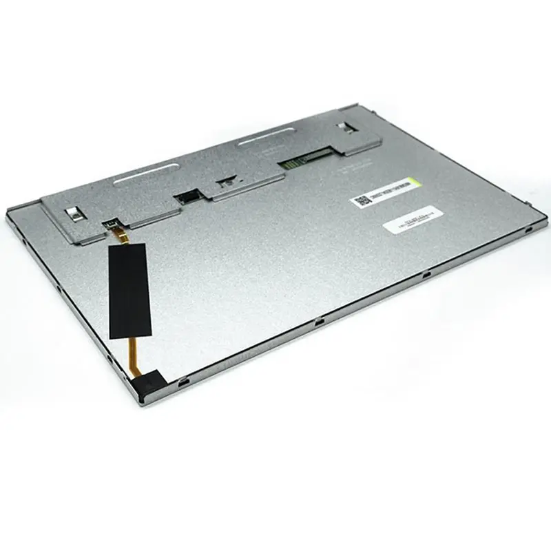
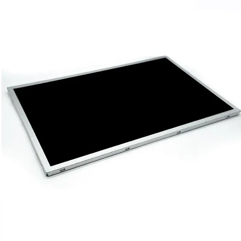
This non-touch 12.1-inch ADS panel combines a native 1280 × 800 workspace, 400-nit typical luminance and LVDS signaling for professional equipment interfaces.
Product Summary
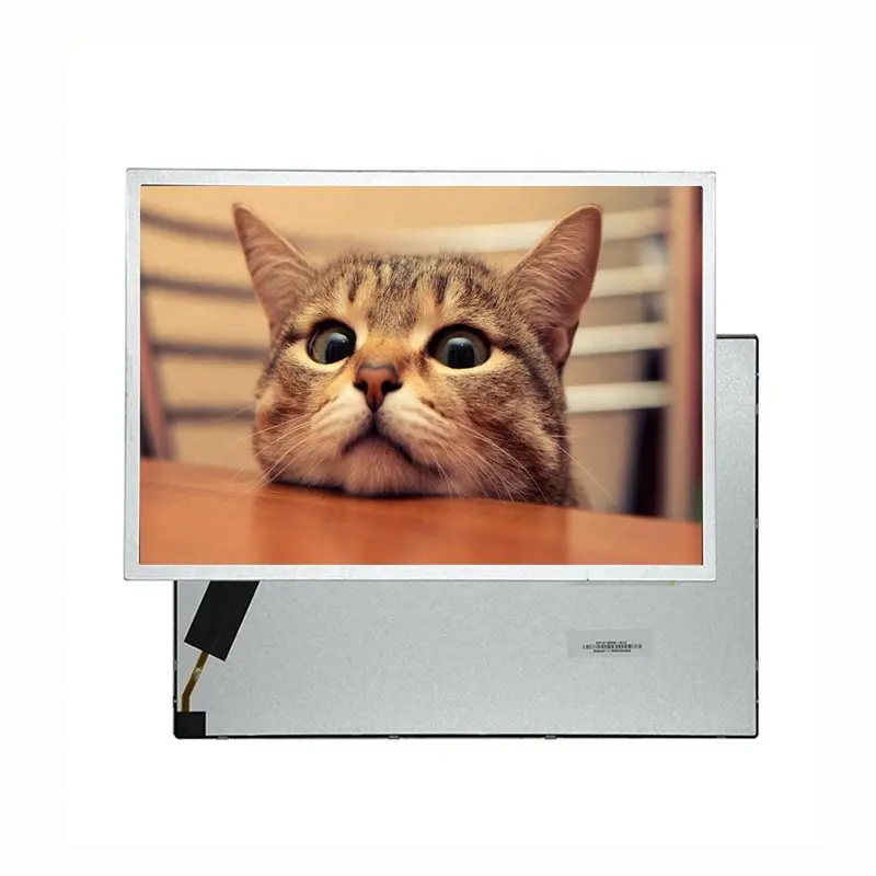
The Medical TFT LCD Module provides a 12.1-inch 16:10 display format for professional instruments, laboratory equipment, monitoring terminals and medical-system integration projects. Its native 1280 × 800 raster offers sufficient workspace for menus, charts, status fields, measurement data and equipment controls while remaining compact enough for enclosed instruments.
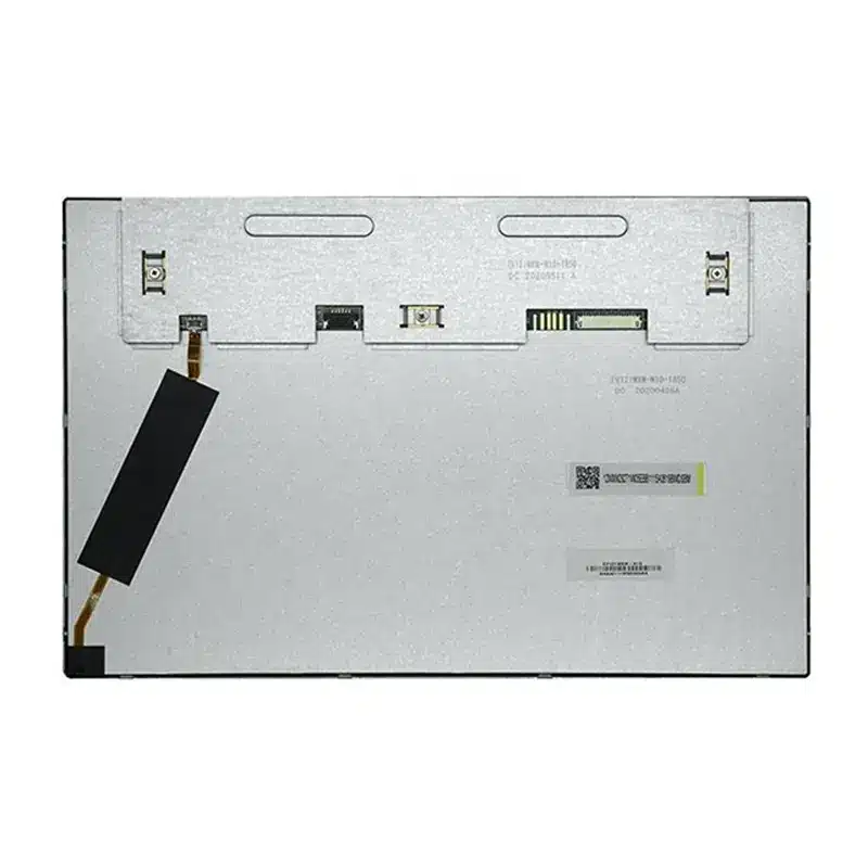
The module combines ADS viewing behavior, normally black operation, 400-nit typical luminance, a 1200:1 contrast ratio and a standard non-touch construction. LVDS is the native panel interface. An HDMI input requires the separately configured controller board rather than connecting directly to the LCD.
Key Specifications
| Parameter | Value |
|---|---|
| Size | 12.1 inch |
| Resolution | 1280 × 800 pixels |
| Aspect ratio | 16:10 |
| Panel type | ADS TFT LCD |
| Display mode | Normally black |
| Luminance | 400 nits typical; 300 nits minimum |
| Contrast ratio | 1200:1 |
| Response time | 25 ms |
| Viewing data | 88/88/88/88 raw sequence |
| Colors | 16.7M |
| Native interface | LVDS, one channel and four pairs |
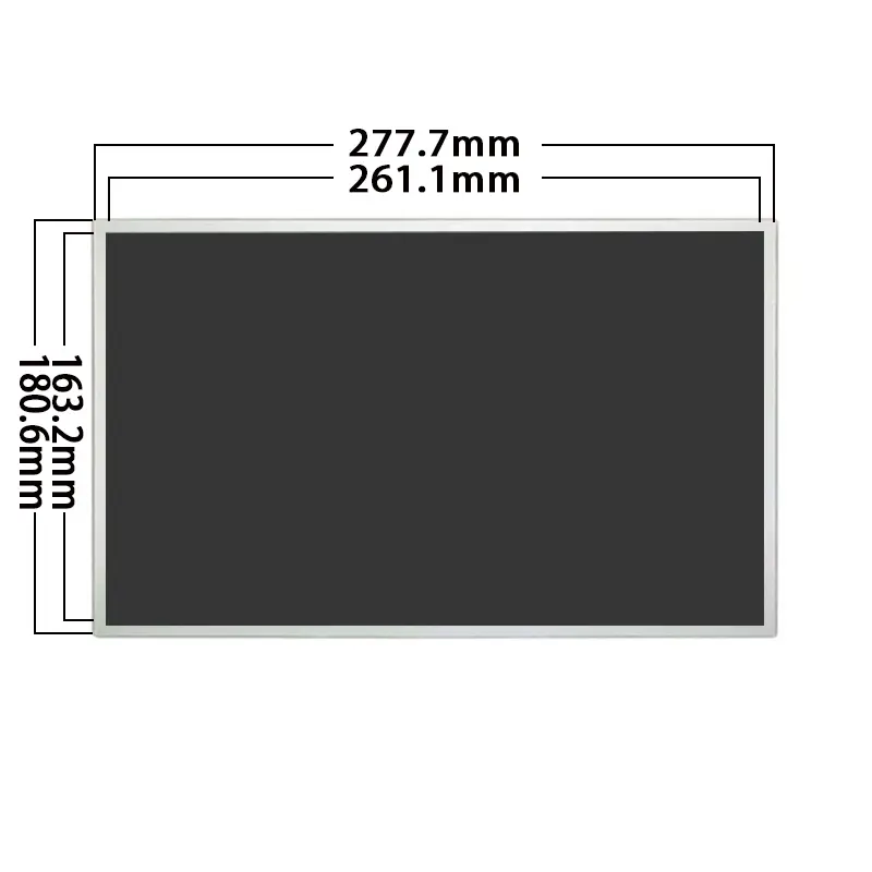
| Active area | 261.12 × 163.2 mm |
| Outline | 277.7 × 180.6 × 8.7 mm |
| Touch | Non-touch |
| Operating temperature | −20°C to +70°C |
| Storage temperature | −30°C to +80°C |
Native 1280 × 800 Equipment Interface Design
16:10 Workspace for Instrument UIs
The 1280 × 800 raster provides a practical balance between information density and physical panel size. The 16:10 format offers additional vertical workspace compared with a similarly sized 16:9 display, which can help organize:
- trend graphs
- measurement tables
- alarm lists
- instrument menus
- equipment-status zones
- operating instructions
- multi-panel dashboards
The 261.12 × 163.2 mm active area should guide the visible opening and content-safe region in the final housing.
Native-Raster Content Preparation
The 1280 × 800 raster should be driven natively to preserve equipment-interface detail.
Text, icons, fine lines and graph labels should be designed for the physical pixel grid. Scaling from another resolution may soften small characters or disturb spacing in dense technical layouts. UI margins must also account for bezel overlap and mechanical tolerance.
ADS Optical Performance in Controlled Lighting
400-Nit Luminance Boundary
The standard panel is specified at 400 nits typical and 300 nits minimum. This configuration is intended primarily for indoor or controlled-light equipment.
A 400-nit panel does not by itself establish outdoor or diagnostic-display performance after cover glass, lighting and system qualification are applied.
Front glass, touch sensors, air gaps, bonding materials, coatings and ambient reflections can reduce effective contrast. The complete display stack should be tested in the intended equipment enclosure and lighting environment.
Contrast, Response and Viewing Behavior
The 1200:1 contrast ratio supports visible separation between dark backgrounds, bright controls and graphical data. Normally black operation is useful for interfaces that rely on dark idle areas or illuminated status elements.
A 25 ms response time is suitable for menus, measurement data, charts and normal interface transitions. It should not be presented as evidence of high-speed imaging performance.
The available viewing data is listed as 88/88/88/88. Because the directional order is not explicitly confirmed, the sequence should remain unassigned until the approved specification identifies its orientation.
LVDS Controller Integration
One-Channel Four-Pair Signal Qualification
The module is described as using one-channel, four-pair LVDS signaling. Before selecting a controller board or releasing a cable, confirm:
- native 1280 × 800 timing
- LVDS mapping
- signal voltage
- bit width
- full connector pinout
- connector pitch
- contact side
- connector orientation
- panel power
- backlight power and control
- cable length and routing
An LVDS interface name does not guarantee timing, voltage, bit-width, connector or pin compatibility with an existing controller.
The full electrical specification must be matched before sample power-up.
HDMI Requires the Optional Controller Board
HDMI is not the native electrical interface of the LCD panel. The selectable HDMI configuration adds a controller board that converts an external HDMI signal into the LVDS timing required by the module.
A project using the HDMI-board option should confirm:
- supported input resolution
- scaling behavior
- board supply requirements
- panel timing
- backlight control
- board outline
- connector locations
- thermal dissipation
- enclosure clearance
DisplayPort, eDP, MIPI DSI, USB and parallel RGB sources also require an appropriate controller or conversion path.
Medical TFT LCD Module Mechanical Integration
Active Area and Visible Opening
The active area is 261.12 × 163.2 mm. This defines the image region and should control:
- bezel opening
- cover-glass window
- UI-safe margins
- front-mask printing
- display alignment
- viewing-angle clearance
Critical information should remain inside the approved visible opening rather than extending to the edge of the active area.
Outline and 8.7 mm Depth
The module outline is 277.7 × 180.6 × 8.7 mm. These dimensions affect enclosure width, mounting depth, rear clearance and cable routing.
An approved mechanical drawing should be used before releasing:
- enclosure tooling
- metal brackets
- front glass
- mounting posts
- LVDS cable length
- controller-board placement
The standard outline does not include an additional touch assembly or the complete HDMI controller-board envelope unless these are defined in the ordered configuration.
Temperature and Equipment-Qualification Boundaries
The module is specified for:
- operation from −20°C to +70°C
- storage from −30°C to +80°C
These ranges support equipment that may experience wider environmental conditions than ordinary office electronics. They do not establish qualification for every medical, laboratory, transport or safety-regulated application.
The module may be evaluated for:
- laboratory analyzers
- professional monitoring terminals
- diagnostic-system user interfaces
- medical-equipment integration
- industrial control panels
- portable test and service equipment
- equipment configuration terminals
- embedded professional instruments
Medical-system use requires system-level review of image requirements, electrical safety, EMC, cleaning materials, enclosure protection, regulatory documentation and risk management. No clinical or diagnostic-image approval is implied by the LCD specification.
Non-Touch and Custom Integration Options
The standard module is non-touch. This configuration is suitable when interaction is provided through:
- physical buttons
- rotary controls
- keypads
- remote controls
- external pointing devices
- supervisory software
Optional project review may include:
- LVDS controller-board matching
- HDMI controller-board configuration
- custom LVDS cable
- connector and pin-definition review
- cover-glass sizing
- surface-treatment review
- optical bonding
- enclosure adaptation
- mounting support
- brightness evaluation
- separate touch-panel development
- packaging and labeling
Custom configurations are generally reviewed from 500 pieces, subject to tooling requirements, material availability and the requested specification. Sample and standard-module quantities are confirmed separately.
Procurement Checklist
Before requesting samples or production approval, submit or confirm:
- native 1280 × 800 timing
- LVDS one-channel/four-pair mapping
- signal voltage and bit width
- complete connector pinout
- connector pitch and orientation
- panel and backlight power requirements
- native LVDS or HDMI-board configuration
- approved mechanical drawing
- active-area and visible-opening position
- cover-glass stack
- touch or non-touch requirement
- 400-nit optical target
- operating and storage conditions
- medical or regulatory requirements
- sample quantity
- annual demand
Sample approval should be completed before controller release, cable manufacture, enclosure tooling or volume procurement.
FAQ
About 12.1 Inch Medical TFT LCD Module
What must be checked before connecting an LVDS controller?
How should equipment UI assets be prepared for 1280 × 800?
Is 400-nit luminance suitable behind cover glass?
Which dimensions should control enclosure release?
What must be confirmed before using the panel in regulated medical equipment?
Freya Yang
+86 18318948097