Freya Yang
+86 18318948097
+852 62667476
7 Inch 1200×1920 MIPI Display Module for Smart Terminals

Model P/N
Size
Resolution
Brightness
Viewing Angle
Connector Type
Operating Temp
Overall(mm)
huisoar
HS0700J16EA
Brand
Panel Size (inch)
Model P/N
Resolution
Brightness (nits)
Viewing Angle
Contrast Ratio
Response Time
Overall (mm)
Active Area (mm)
Refresh Rate
Bezel Opening
Display Colors
Panel Type
Connector Type
Surface Treatment
Operating Temp
Touchscreen Type
Storage Temp
Work Mode
Pixel Format
Touch Interface
Control Type
Unit Input Voltage
Product Appearance Size
Operating Environment
Designed For
7 Inch 1200x1920 MIPI Display Module for Smart Terminals
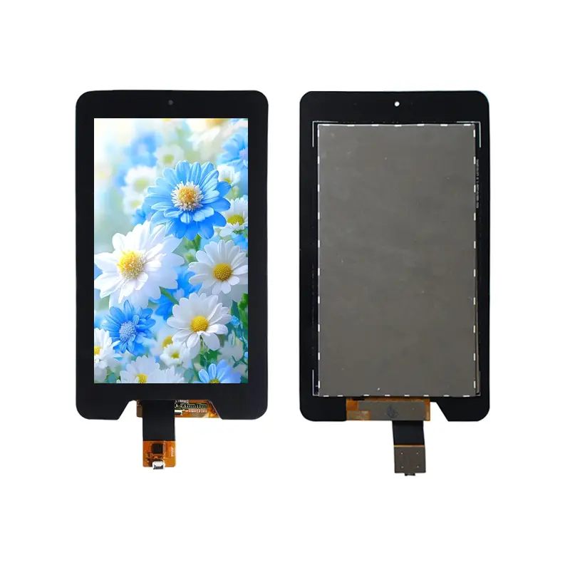
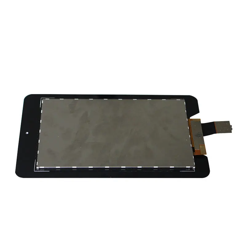
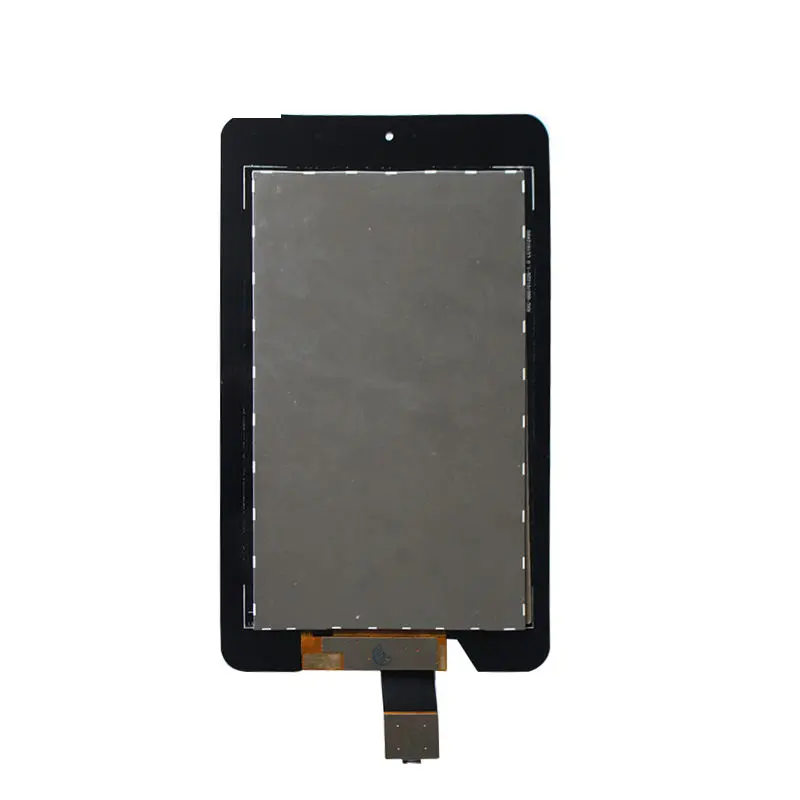
A high-resolution LTPS portrait display with 40-pin MIPI imaging and separate GT911 I²C capacitive-touch control.
The 1200x1920 MIPI Display Module provides a tall portrait canvas for embedded products that need dense graphics, app-style navigation and touch interaction in a narrow front-panel format. Its 7.02-inch LTPS TFT uses a native 1200 × 1920 resolution, normally-black operation, a 40-pin MIPI connection and a capacitive-touch assembly with GT911 I²C control.
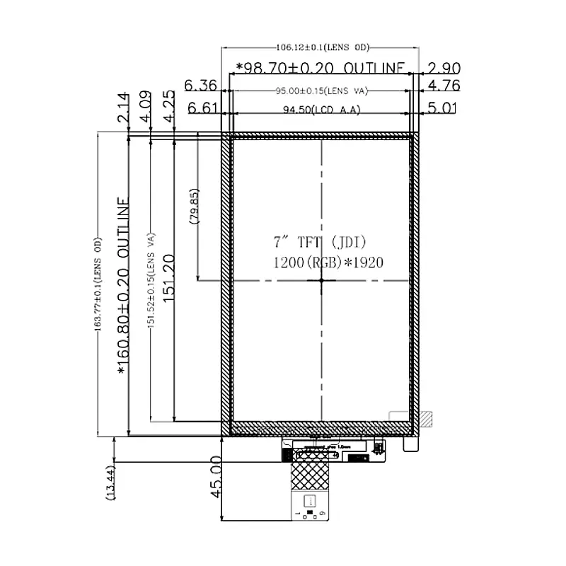
The LCD active area is 94.5 × 151.2 mm, while the LCD-only outline is 97.3 × 159.4 × 2.2 mm typical. The represented high-brightness configuration is specified at 1000 cd/m² typical, but final readability must be evaluated with the actual cover glass, touch stack, ambient light and UI design.
Key Specifications at a Glance
| Parameter | Confirmed value |
|---|---|
| Display size | 7.02 inch |
| Resolution | 1200 × 1920 pixels |
| Panel technology | LTPS TFT active matrix |
| Display mode | Normally black |
| Viewing characteristic | Free viewing direction |
| Color depth | 16.7 million colors by 8-bit |
| LCD interface | MIPI 4-lane |
| LCD connection | 40-pin FPC |
| Touch type | Capacitive touch |
| Touch controller | GT911 |
| Touch interface | I²C |
| Active area | 94.5 × 151.2 mm |
| LCD outline | 97.3 × 159.4 × 2.2 mm typical |
| Pixel pitch | 0.07875 × 0.07875 mm |
| Surface treatment | Hard coating |
| Luminance | 1000 cd/m² typical |
| Cover glass | 0.70 mm |
| Backlight circuit | 16 LEDs with 80 mA branch-total reference |
The approved LCD and touch drawings must govern final electrical and mechanical release.
1200×1920 Portrait UI Performance
The 1200 × 1920 format provides a dense 10:16 portrait workspace for vertical menus, status cards, lists, forms, alerts and app-like navigation.
UI layout advantages
The portrait area can support:
- Stacked status panels
- Long parameter lists
- Access-control workflows
- Building-control menus
- Service and diagnostic pages
- Product-selection interfaces
- Message and alarm histories
- QR or barcode workflows
- Image and video preview
- Tablet-style navigation
Graphics should be developed at the native resolution wherever practical. Scaling from lower resolutions can reduce text clarity and weaken the benefit of the high pixel density.
Active area and image density
The 94.5 × 151.2 mm active area places 1200 × 1920 pixels in a compact vertical space. This supports fine text and detailed icons, but it also requires careful UI scaling so buttons and touch targets remain physically usable.
A high pixel count does not automatically make small interface elements easier to operate. Font size, touch-target dimensions and viewing distance should be validated on the physical sample.
LTPS Normally-Black Display Structure
The panel uses an LTPS TFT active matrix and normally-black operation.
LTPS integration value
LTPS is suitable for compact high-resolution displays because it supports a dense pixel structure within a slim module. The technology identification does not by itself establish power consumption, response time or lifetime performance, so those values should be taken only from the approved module specification.
Normally-black optical behavior
A normally-black panel can support dark-theme interfaces, high-contrast status graphics and app-style visual design. Final black level and contrast depend on the LCD, backlight, touch stack, cover glass and ambient environment.
The supplied specification identifies a free viewing direction but does not give numerical angular limits. Viewing consistency should therefore be approved with samples from the intended mounting orientation.
40-Pin MIPI Host Qualification
The LCD uses a 40-pin MIPI connection and is described as a MIPI 4-lane module. The host processor must provide the correct lane configuration, timing, voltage domains and control signals.
A 40-pin MIPI connector does not guarantee host compatibility.
Checks before controller-board release
Confirm:
- Native 1200×1920 timing
- MIPI lane count
- Data-lane order and polarity
- Clock-lane mapping
- Complete 40-pin assignment
- Logic and panel voltage domains
- Reset and enable signals
- Backlight connections
- FPC pitch and contact side
- Pin-1 orientation
- Required initialization information
- Power sequencing from the approved specification
MIPI terminology alone does not prove that a specific processor, development board or cable can operate the module.
Non-MIPI hosts
HDMI, LVDS, eDP, parallel RGB and USB video outputs cannot drive the LCD directly without suitable conversion hardware.
A bridge or controller should be selected using the complete MIPI timing, lane map, resolution, voltage and backlight requirements rather than screen size alone.
1200x1920 MIPI Display Module Touch Integration
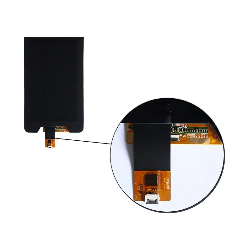
The display image and touch input use separate communication paths. MIPI carries the LCD image data, while the GT911 touch controller communicates through I²C.
The MIPI image path and GT911 I²C touch path are separate interfaces.
GT911 I²C route
The touch connection should be checked for:
- SCL and SDA assignment
- Touch-controller supply
- I/O voltage
- Reset signal
- Interrupt signal
- Grounding
- FPC contact orientation
- Coordinate mapping
- Display rotation
- Host-driver support
The identified GT911 controller does not by itself prove multi-touch count, glove operation, water rejection or operating-system compatibility.
Cover-glass and sensor structure
The touch drawing identifies a 0.70 mm cover glass and a separate sensor layer. The complete assembly is therefore thicker and larger than the LCD-only outline.
Touch performance should be validated after the final cover printing, border design, bonding method and enclosure are defined.
High-Brightness Configuration and Environment
The represented module configuration is specified at 1000 cd/m² typical.
What 1000 cd/m² means for selection
The high-brightness configuration can be evaluated for bright indoor spaces, equipment near windows and other demanding ambient-light conditions. It should not automatically be described as sunlight readable because outdoor performance also depends on reflections, cover-glass transmission, touch-layer losses, contrast and direct-sun conditions.
Backlight-driver qualification
The drawing shows a 16-LED circuit with four branches and an 80 mA total branch-current reference. The final driver must be selected from the complete voltage, current, dimming and thermal requirements.
LED count alone does not establish:
- Required boost voltage
- Dimming method
- Maximum electrical power
- Backlight lifetime
- Thermal limit
- Minimum or maximum luminance
These items require the approved electrical specification.
Mechanical Integration and Enclosure Fit
The LCD-only structure and the complete touch assembly use different dimensions.
LCD-only dimensions
- Active area: 94.5 × 151.2 mm
- LCD outline: 97.3 × 159.4 × 2.2 mm typical
- Pixel pitch: 0.07875 × 0.07875 mm
Complete touch assembly
The touch drawing indicates an assembly outline of approximately 106.12 × 168.80 mm. This value should be confirmed against the final drawing revision before tooling.
The complete assembly may include:
- LCD cell
- Backlight
- Sensor glass
- Cover glass
- Adhesive
- Touch FPC
- LCD FPC
- Controller components
- Border printing
Enclosure checklist
Verify:
- Cover-lens outline
- Lens viewing area
- Active image area
- Bezel overlap
- Complete stack thickness
- FPC exit position
- FPC bend radius
- Connector clearance
- Camera or sensor opening
- Mounting tape
- Bonding area
- Touch-controller component clearance
The approved LCD-plus-touch drawing—not the marketplace outline alone—should determine the enclosure opening.
Recommended Applications
This configuration can be evaluated for:
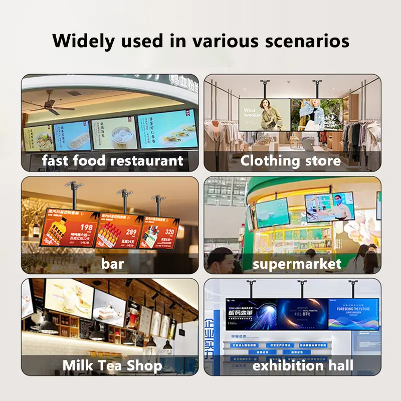
- Smart control terminals
- Vertical industrial HMI panels
- Building-control interfaces
- Industrial handhelds
- Portable test and service equipment
- Tablet-style embedded products
- Access and information terminals
- AV display terminals
- Smart appliance interfaces
- Compact diagnostic equipment
A different module may be preferable when the host does not support native MIPI, the project needs a landscape UI, lower brightness is sufficient, or the enclosure cannot accommodate the complete touch stack.
Customization and Project Review
Project-specific review may include:
- Touch cover outline
- Cover-glass printing
- Touch-controller configuration
- LCD and touch FPC design
- MIPI timing and pin definition
- Brightness configuration
- Backlight-driver matching
- Cover treatment
- Mechanical stack
- Optical bonding
- Controller or bridge-board selection
- Packaging and branding
Custom configurations are generally reviewed from 1,000 pieces, subject to tooling requirements, material availability and the requested specification. Samples and standard-module quantities are confirmed separately.
Procurement Checklist
Before sample approval, confirm:
- Native 1200×1920 timing
- MIPI 4-lane support
- Complete 40-pin assignment
- Lane order and polarity
- LCD voltage domains
- Reset and enable signals
- FPC pitch and contact side
- Pin-1 orientation
- Backlight voltage and current requirements
- Brightness environment
- GT911 controller revision
- I²C voltage and address
- Reset and interrupt routing
- Required touch-point count
- Host-driver support
- Display and touch orientation
- Active area: 94.5 × 151.2 mm
- LCD outline: 97.3 × 159.4 × 2.2 mm typical
- Complete touch outline and stack
- Cover-glass printing
- Bezel opening
- FPC and connector clearance
- Sample quantity
- Annual demand
- Controller-board requirement
- Production schedule
FAQ
About 1200x1920 MIPI Display Module
What must be checked before connecting this module to another 40-pin MIPI host?
How are the display and touch interfaces connected?
Which dimensions should control the enclosure design?
When should the 1000 cd/m² configuration be selected?
What information is required for sample qualification?
Do you offer samples for evaluation before placing a bulk order?
Yes, samples are typically available for evaluation before bulk orders. Please contact our sales team to request a sample of the HS0700J16EA module. We will confirm lead time and any applicable sample fees. Evaluation of the display with your specific cover glass and touch stack is recommended to verify readability under your ambient light conditions.
What touch screen technologies do you support (e.g., capacitive, resistive, in-cell)?
The touch panel is customizable, meaning we can integrate different touch solutions based on your requirements. For resistive or in-cell touch options, please confirm with our engineering team as the current product is configured for capacitive touch.
Do you offer displays with high refresh rates (e.g., 120Hz) for smooth graphics in transportation information systems?
The HS0700J16EA has a standard refresh rate of 60 Hz. For applications requiring higher refresh rates like 120 Hz, we recommend discussing your specific needs with our engineering team. We can evaluate if a custom variant or alternative panel is suitable for smooth graphics in transportation information systems.
Can you customize the mechanical dimensions and mounting holes of a standard LCD panel to fit our specific enclosure design?
Yes, we can customize the mechanical dimensions and mounting holes to fit your enclosure design. The touch panel is customizable, and the LCD module outline can be adjusted within technical limits. Please provide your mechanical drawing and requirements to our sales team for feasibility assessment and lead time estimation.
What interface options are available (e.g., LVDS, eDP, MIPI) for your panels?
This model, the HS0700J16EA, uses a 40-pin MIPI interface. MIPI is the standard interface for this 7.0-inch 1200×1920 display module. If your application requires a different interface, please contact us with your project requirements so we can recommend an alternative display or discuss a custom solution.
Freya Yang
+86 18318948097