Freya Yang
+86 18318948097
+852 62667476
7 Inch MIPI LCD Module with CTP for Embedded HMI
Model P/N
Size
Resolution
Brightness
Viewing Angle
Connector Type
Operating Temp
Overall(mm)
huisoar
HSO70ICN-PB1
Brand
Panel Size (inch)
Model P/N
Resolution
Brightness (nits)
Viewing Angle
Response Time
Overall (mm)
Active Area (mm)
Refresh Rate
Display Colors
Panel Type
Connector Type
Surface Treatment
Operating Temp
Touchscreen Type
Storage Temp
Work Mode
Pixel Format
Input Voltage (V)
Touch Interface
Control Type
Product Appearance Size
Protective Glass Specification
Motherboard Type
Designed For
7 Inch MIPI LCD Module with CTP for Embedded HMI
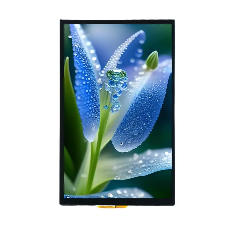
This portrait IPS display combines an 800×1280 MIPI image path with an optional GT911-controlled capacitive-touch assembly.
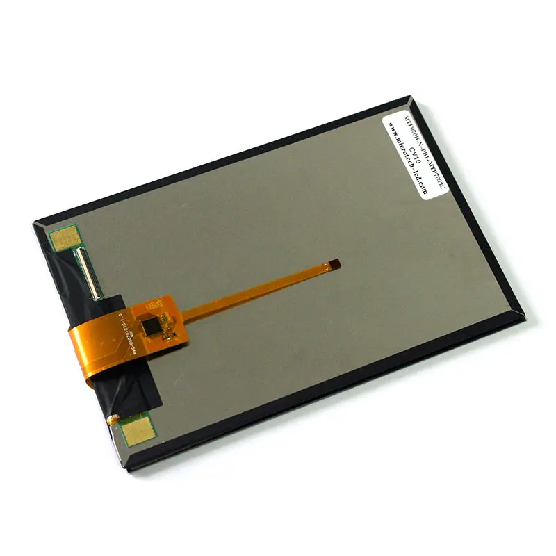
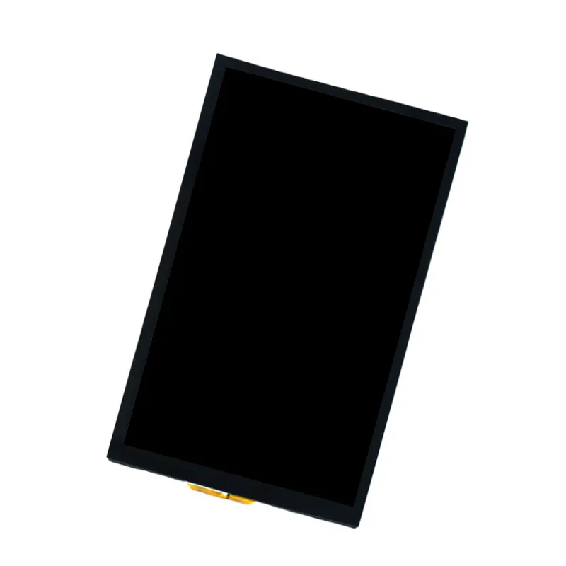
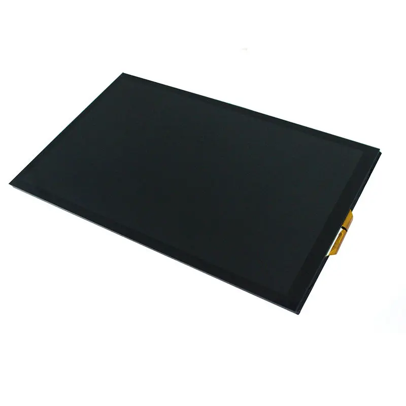
The 7 Inch MIPI LCD Module with CTP is a portrait-format display component for embedded systems that need a compact visual interface and configurable touch input. Its 800×1280 resolution, MIPI display connection, 40-pin LCD FPC, and optional capacitive-touch structure make it suitable for vertical control panels, smart terminals, connected appliances, and portable operator equipment.
The display and touchscreen use separate electrical paths. MIPI carries the LCD image data, while the GT911-controlled touch assembly uses a separate I²C control connection.
Key Specifications at a Glance
| Parameter | Value |
|---|---|
| Display size | 7.0 inch |
| Resolution | 800 × 1280 pixels |
| Panel technology | IPS TFT LCD |
| Display interface | MIPI |
| LCD connector | 40-pin FPC |
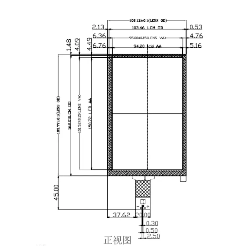
| Active area | 94.20 × 150.70 mm |
| LCD outline | 97.35 × 162.03 × 2.30 mm |
| Luminance | 350 cd/m² |
| Touch configuration | Optional capacitive-touch assembly |
| Touch controller | GT911 |
| Touch-control path | I²C |
| Touch-lens outline | 108.12 × 167.74 mm |
A production design should be approved against the complete LCD timing, MIPI lane configuration, pin assignments, touch wiring, voltage domains, backlight requirements, and mechanical drawings.
Portrait 800×1280 Interface Design
The 800×1280 pixel format provides a tall interface area for menus, process values, alerts, lists, setup pages, and touch controls. It is particularly useful where a vertical enclosure offers more space than a landscape display opening.
Native portrait UI planning
Graphics should be generated for the native 800×1280 framebuffer whenever possible. This avoids unnecessary scaling and gives UI designers direct control over text size, icon spacing, and touch-target placement.
The 94.20 × 150.70 mm active area provides a physical reference for evaluating character size and control density on the actual panel.
IPS panel configuration
The IPS TFT structure supports use in equipment where the operator may not remain directly in front of the screen. Numeric viewing-angle limits are not defined here, so final optical acceptance should use production samples installed behind the planned cover structure.
Controlled-light luminance
The module is specified at 350 cd/m². This is appropriate for indoor and controlled-light equipment but does not establish direct-sunlight readability.
The finished brightness will also depend on the cover glass, ITO layer, adhesive stack, air gaps, surface treatment, and enclosure geometry.
MIPI Display Compatibility
MIPI DSI is a host-to-display interface, but the interface name alone does not establish plug-and-play compatibility. The processor and display must agree on their physical and protocol requirements.
Host parameters to confirm
Before releasing the controller PCB, verify:
- MIPI lane count
- Lane mapping
- Clock and data-lane assignments
- D-PHY timing
- Video or command operating mode
- Native 800×1280 timing
- Pixel format
- Panel reset and enable behavior
- LCD voltage requirements
- Backlight enable and control
- Complete 40-pin assignment
- FPC pitch, orientation, and contact side
A host that supports another MIPI screen is not automatically compatible with this module.
40-pin FPC qualification
A matching 40-pin connector does not guarantee electrical compatibility.
The connector may combine MIPI lanes, power, ground, reset, panel control, backlight, identification, and other functions. The complete pinout and mating-connector specification must therefore be checked before PCB layout.
Non-MIPI video inputs
HDMI, DisplayPort, eDP, LVDS, RGB, and USB video do not connect directly to the native MIPI display input. A bridge or controller board is required when the host cannot generate the approved MIPI signal.
Touch Control and GT911 Integration
The capacitive-touch configuration uses a GT911 controller and a separate touch FPC. GT911 identifies the touch-control component; it does not define the LCD image interface or prove the display’s MIPI requirements.
Separate I²C touch path
The touch drawing identifies clock, data, reset, interrupt, ground, and supply functions on the touch connector. This means the touchscreen should be designed as an independent I²C peripheral alongside the MIPI display path.
Firmware planning should include:
- I²C bus routing
- Reset control
- Interrupt input
- Touch-controller address confirmation
- Coordinate orientation
- Display-to-touch alignment
- Cover-lens calibration
- Driver and operating-system support
Optional CTP configuration
Capacitive touch is an available assembly option and should be specified explicitly in the order. LCD-only and LCD-plus-CTP configurations may have different dimensions, FPC routes, optical stacks, and approval drawings.
Voltage reference requires confirmation
The available technical material contains different voltage references for the touch configuration. One value indicates 2.8–3.3 V, while the touch pin assignment marks 1.8 V signal domains.
The production pinout must resolve the supply and logic-voltage requirements before the host schematic is finalized.
Mechanical Stack of the 7 Inch MIPI LCD Module with CTP
The LCD outline measures 97.35 × 162.03 × 2.30 mm. The capacitive-touch assembly uses a larger cover-lens footprint, so enclosure dimensions must not be taken from the LCD outline alone.
LCD and touch dimensions
| Mechanical item | Value |
|---|---|
| LCD active area | 94.20 × 150.70 mm |
| LCD outline | 97.35 × 162.03 × 2.30 mm |
| Touch-lens outline | 108.12 × 167.74 mm |
| Touch-stack thickness | 1.40 ± 0.20 mm |
| Maximum assembled thickness | 4.50 mm |
| Cover glass | 0.70 mm |
| ITO glass | 0.55 mm |
Enclosure planning
The mechanical design should account for:
- Lens overhang beyond the LCD
- Active-area centering
- Black-mask and viewing-area boundaries
- Adhesive and tolerance stack
- LCD and touch FPC exits
- Connector insertion clearance
- Backlight and rear-component clearance
- Bezel support without pressure on the active area
- Service and replacement access
FPC routing
The display and touch FPCs should not be sharply folded or trapped against mounting features. Separate routing space helps reduce mechanical stress and simplifies assembly inspection.
Optical Stack and Touch Transmittance
The touch construction uses cover glass, ITO glass, FPC, and adhesive. Its listed light transmittance is at least 86%.
Effect on final brightness
Touch-panel transmittance does not equal final system luminance. The visible result also depends on LCD luminance, cover printing, adhesive, surface reflections, air gaps, and any protective window added by the enclosure.
A sample should be evaluated in the intended lighting environment before the optical target is approved.
Cover-glass review
The specified 0.70 mm cover glass and 0.55 mm ITO glass define the current touch structure. Different cover thicknesses, edge treatments, printing, or lens dimensions require separate optical, mechanical, and touch-performance review.
Recommended Applications
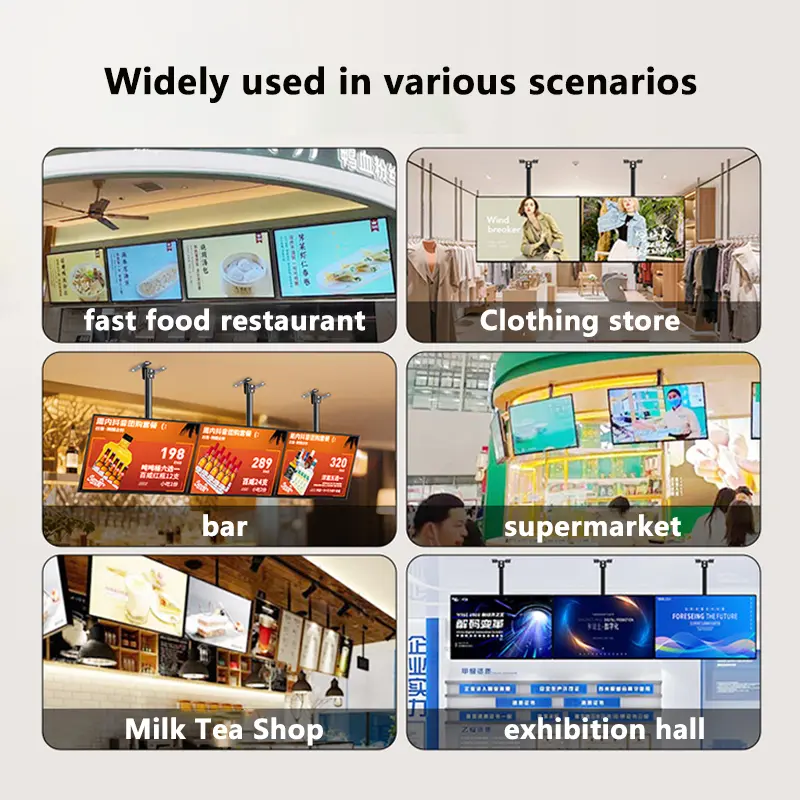
The module can be evaluated for:
- Portrait embedded HMI panels
- Smart-home control interfaces
- Building-control terminals
- Connected appliance controls
- Portable test and service equipment
- Compact operator terminals
- Equipment setup interfaces
- Vertical information and status panels
Medical, automotive, outdoor, safety-critical, and regulated applications require separate environmental, reliability, certification, and system-level qualification.
Customization and Project Review
Project-specific review may cover:
- Touch or non-touch configuration
- Cover-lens shape and printing
- FPC shape and exit location
- Pin definition
- MIPI timing and host matching
- Touch-controller routing
- Brightness target
- Mechanical stack
- Adhesive and bonding structure
- Controller or bridge-board requirement
Custom configurations are generally reviewed from 1,000 pieces, subject to tooling requirements, material availability, and the requested specification. Samples and standard-module quantities are confirmed separately.
Procurement and Sample Approval Checklist
Confirm the following before the production PCB and enclosure are released:
- Native 800×1280 display timing
- MIPI lane count and lane mapping
- MIPI operating mode and D-PHY timing
- Complete 40-pin LCD pinout
- LCD FPC pitch, contact side, and orientation
- Complete 6-pin touch assignment
- GT911 I²C address and control requirements
- Touch reset and interrupt routing
- LCD, touch, and logic voltage domains
- Backlight-driver requirements
- 94.20 × 150.70 mm active area
- 97.35 × 162.03 × 2.30 mm LCD outline
- 108.12 × 167.74 mm touch-lens outline
- 4.50 mm maximum assembled thickness
- Cover printing and viewing opening
- Target lighting environment
- Touch or non-touch order configuration
- Sample quantity
- Annual demand
- Production schedule
- Controller or bridge-board requirement
FAQ
About 7 Inch MIPI LCD Module with CTP
What must be checked before connecting this module to an existing MIPI host?
Does the 40-pin FPC make it interchangeable with another 7-inch MIPI panel?
How should the MIPI display and GT911 touchscreen be connected?
Which dimensions should control the enclosure design?
Which voltage value should be used for the touch interface?
When is a bridge or controller board required?
Freya Yang
+86 18318948097