~
~
~
~
~
~
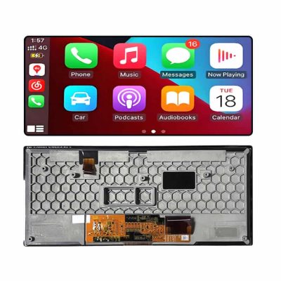
C123HAX04.K 96-Pin In-Cell Vehicle LCD Cell AUO
Model P/N
Size
Resolution
Brightness
Viewing Angle
Connector Type
Operating Temp
Overall(mm)
auo
C123HAX04.K
Brand
Panel Size (inch)
Model P/N
Resolution
Viewing Angle
Contrast Ratio
Response Time
Overall (mm)
Active Area (mm)
Refresh Rate
Display Colors
Panel Type
Connector Type
Surface Treatment
Operating Temp
Touchscreen Type
Storage Temp
Work Mode
Pixel Format
Input Voltage (V)
Touch Interface
Designed For
Product Details
Product Overview
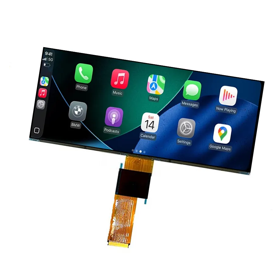
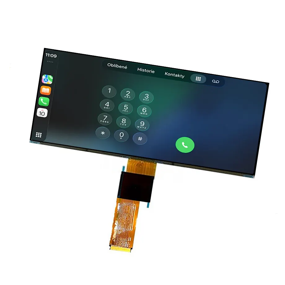
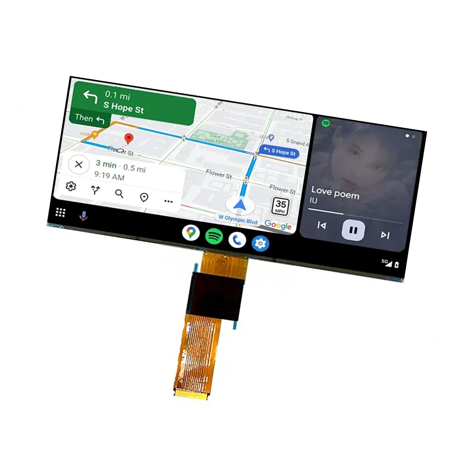
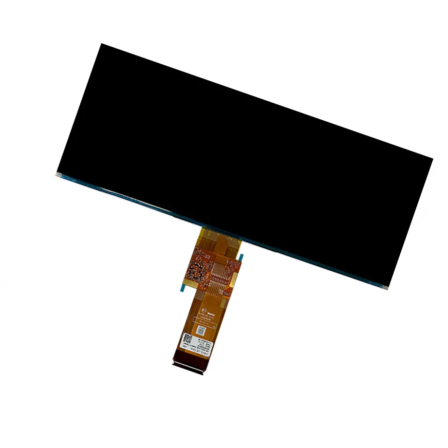
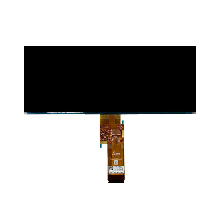
C123HAX04.K 96-Pin In-Cell Vehicle LCD Cell is a 12.3-inch AUO LTPS TFT-LCD FOG cell developed around a wide 1920(RGB)×720 raster with an 8:3 image format. The active image area is 292.032 × 109.512 mm inside a 297.03 × 118.84 × 0.65 mm outline. Its AHVA normally-black transmissive mode is specified at 1100:1 typical contrast, 80/80/80/80 typical viewing-angle values at CR≥10, 16.7M colors with 71% NTSC wording and a hard-coated front surface. The cell itself has no integrated backlight, so the recorded luminance is 0 cd/m² and optical output depends on the external illumination system.
This exact variant combines in-cell touch with an I²C touch-control path and a dual-channel 8-bit LVDS display interface on a 96-pin 0.5 mm FPC. It operates at 60 Hz and uses a five-rail panel power set: 3.3 V VCI, 7.15 V AVDD, 7.15 V AVEE, 14 V VGH and -1.3 V VGL typical. Transmissivity is 4.5% typical with polarizer, response time is 25 ms maximum Tr+Td, and the operating/storage limits are -40 to 85 °C / -40 to 95 °C. The product is documented for Automotive Display use, but those component facts should not be expanded into an unsupported vehicle qualification or certification claim.
Three Core Buyer Value Propositions
1. Integrated in-cell touch reduces stack height while keeping touch qualification explicit
The touch sensor is integrated at the panel level and communicates over I²C, so an automotive HMI can avoid a separate thick add-on touch panel in the basic display stack. That can help package depth, optical interfaces and bezel design. It also creates an exact electronics requirement: the target ECU must support the panel's touch-controller signaling, reset and interrupt behavior, coordinate mapping and sleep/wake sequence. “In-cell touch” does not mean every I²C host or cover-lens stack is automatically compatible.
2. A 96-pin dual-channel LVDS path gives controller and harness teams a concrete electrical target
The 1920×720 raster is transported over dual-channel 8-bit LVDS through a dense 96-contact FPC. That combination is highly specific compared with generic 12.3-inch bar displays, and it helps screen out substitutes with different pin counts or lane architectures before sampling. Exact pin assignment, clock mapping, control signals and touch lines must still be taken from the controlled drawing. The connector count is a starting point for design control, not a claim of interchangeability.
3. -40 to 85 °C operation and five panel rails expose real vehicle-integration work early
The exact-model operating boundary reaches -40 °C and the storage limit reaches 95 °C, useful component-level inputs for vehicle-cabin thermal planning. At the same time, the five-rail supply set requires more deliberate PMIC sequencing than a single-voltage module. Electrical validation should combine temperature extremes, panel initialization, touch behavior and LVDS stability because cold-start and hot-soak conditions can expose timing or supply-margin issues that are not visible on a room-temperature bench.
Key Specifications at a Glance
| Parameter | Confirmed value |
|---|---|
| Manufacturer / model | AUO C123HAX04.K |
| Display size / format | 12.3 inch, 1920×720, 8:3 |
| Panel type | LTPS TFT-LCD, CELL (FOG) |
| Active area | 292.032 × 109.512 mm |
| Outline | 297.03 × 118.84 × 0.65 mm |
| Display mode | AHVA, Normally Black, Transmissive |
| Contrast ratio | 1100:1 typical |
| Viewing-angle values | 80/80/80/80 typical at CR≥10 |
| Response time | 25 ms maximum Tr+Td |
| Colors | 16.7M, 71% NTSC |
| Surface | Hard coating |
| Transmissivity | 4.5% typical with polarizer |
| Refresh rate | 60 Hz |
| Display interface | LVDS, 2 channels, 8-bit; 96-pin 0.5 mm FPC |
| Touch | In-Cell Touch, I²C |
| Panel input rails | 3.3 / 7.15 / 7.15 / 14 / -1.3 V typical (VCI / AVDD / AVEE / VGH / VGL) |
| Backlight | External; cell luminance 0 cd/m² |
| Operating / storage | -40 to 85 °C / -40 to 95 °C |
| Application | Automotive Display |
Why this 8:3 cell should be treated as a bar-format vehicle display component
The 1920×720 raster creates a very wide visual canvas for multi-zone vehicle information, navigation, climate controls or passenger-facing content. AUO's car display portfolio shows how automotive displays span dashboard and in-vehicle information applications, but the exact function of C123HAX04.K remains a system-design decision. The component specification establishes the physical and electrical foundation; it does not define the finished vehicle HMI layout.
C123HAX04.K 96-Pin In-Cell Vehicle LCD Cell should therefore be evaluated as a bare optical/electronic cell rather than as a complete dashboard module. A production system still needs a backlight, optical films, mechanical carrier, cover lens, controller, power conversion and environmental protection appropriate to the target location. If a supplier describes another 12.3-inch 1920×720 panel as a substitute, the exact FPC, supply rails, touch implementation and thermal range must be compared before approval.
What does 4.5% transmissivity mean for backlight design?
The 4.5% typical transmissivity value with polarizer describes how much of the backlight energy passes through the LCD optical stack under the specified condition. It is not a finished-display brightness figure. Because the cell is supplied without a backlight and its luminance entry is 0 cd/m², the optical engineer must size the external LED source, light guide, diffuser films and power budget to reach the finished-system luminance target.
Vehicle applications can require very different luminance depending on mounting position, ambient light, cover treatment and day/night dimming strategy. The correct backlight cannot be selected by multiplying transmissivity by an unrelated LED specification. Prototype the complete stack, measure white luminance and uniformity across temperature, and check dimming behavior at the darkest intended night mode. Thermal loading and LED efficiency should be evaluated inside the production enclosure rather than on an open optical bench.
Dual-channel LVDS and the 96-pin FPC require exact signal mapping
Texas Instruments' LVDS training resources explain the differential-signaling principles behind low-voltage differential interfaces. For this exact AUO cell, the practical design inputs are two 8-bit LVDS channels, a 96-pin 0.5 mm FPC and 60 Hz native timing. Those facts do not identify every signal location or control line; the controlled panel drawing remains necessary before harness or controller release.
The high pin count is partly important because the assembly also incorporates touch and several power/control functions. Cable design should verify differential-pair routing, ground distribution, connector insertion, touch/control signals and the mechanical bend path. In vehicle prototypes, test repeated ignition-style power cycles, display wake-up, EMI-sensitive operating states and touch activity together. An LVDS controller that can generate 1920×720 is not sufficient evidence if its mapping or initialization differs from the AUO implementation.
Five supply rails make sequencing a first-class engineering requirement
The 3.3 V VCI, positive and negative analog rails, 14 V gate-high rail and -1.3 V gate-low rail support different functions inside the LCD drive structure. They should not be collapsed into a single “panel voltage.” The PMIC and enable logic need to respect exact tolerances, rise/fall timing and discharge behavior. Incorrect sequencing can lead to startup artifacts, latch-up risk or unreliable initialization even when each nominal voltage measures correctly after power-on.
Cold-start testing at the documented -40 °C operating boundary is especially important because regulator behavior, flex resistance and liquid-crystal response can all shift with temperature. Repeat power-up after thermal soak rather than relying only on continuous operation. At the hot end, verify that rail regulation, touch communication and image stability remain within acceptance limits. The wide component temperature range supports a vehicle design study but does not by itself prove compliance with an OEM reliability standard.
In-cell touch needs separate firmware and cover-stack validation
The touch architecture is built into the display cell and communicates via I²C. That avoids assuming an external touch-panel controller, but it still leaves several system questions: bus voltage, address, interrupt behavior, reset sequence, coordinate mapping and any firmware-specific tuning. Touch performance should be tested after the production cover lens and bonding stack are assembled because glass thickness, coatings and grounding can influence sensitivity and noise immunity.
For automotive interfaces, include wet or gloved use only if those modes are actual product requirements and if the exact touch system supports them; no such capability is claimed from the present component data. Evaluate false touches during conducted/radiated noise testing, display transitions and backlight PWM operation. Treat the touch function as an integrated subsystem requiring qualification, not as a generic feature automatically inherited by any controller board.
Wide-temperature optical behavior deserves more than an electrical pass/fail
The documented operating range is -40 to 85 °C and storage is -40 to 95 °C. At temperature extremes, image response, black level, contrast and touch behavior can differ from room-temperature results. The specified 25 ms maximum Tr+Td response is a panel transition metric under its defined test basis; it should not be converted into system latency or assumed to remain identical under every thermal condition.
A useful validation matrix includes cold startup, warm-up transition, high-temperature sustained images, day/night dimming and repeated thermal cycling on production-intent assemblies. Inspect mura, uniformity, stuck/slow transitions and touch tracking after exposure. This engineering approach respects the exact-model wide-temperature data without turning it into an unsupported declaration of automotive grade, functional safety or regulatory compliance.
Application fit: instrument clusters, center information and wide vehicle HMI layouts
C123HAX04.K 96-Pin In-Cell Vehicle LCD Cell is explicitly documented for Automotive Display use. Its 12.3-inch bar geometry, integrated touch and wide operating temperature make it relevant to vehicle HMI architectures that need a wide interactive surface. Potential placements include center information, climate/infotainment or other wide-format cockpit zones when the target mechanical, optical and electrical requirements match the confirmed component data.
Those are application scenarios, not exact vehicle-fit claims. No specific car model, OEM connector, dashboard assembly or safety integrity level is established. A finished vehicle display must add its own backlight, controller, housing, optical bonding, EMC design and validation plan. Exact-model sourcing should preserve the `.K` suffix because the closely related `.U` version uses a different connector/power architecture and should not be treated as electrically interchangeable.
Procurement and validation checklist
- Lock AUO C123HAX04.K and the exact `.K` suffix in the BOM.
- Validate native 1920×720 timing at 60 Hz over dual-channel 8-bit LVDS.
- Confirm the 96-pin 0.5 mm FPC, exact signal map and mechanical fold direction.
- Design and sequence the 3.3 / 7.15 / 7.15 / 14 / -1.3 V panel rails from the controlled specification.
- Qualify the in-cell I²C touch path after the production cover and grounding design are assembled.
- Design the external backlight around the 4.5% transmissivity and finished-system luminance target.
- Test cold startup at -40 °C and sustained operation through the documented 85 °C limit.
- Keep panel mass blank until exact-model evidence or a controlled sample measurement is available.
- Do not convert Automotive Display application wording into an unsupported certification or vehicle-fit claim.
For qualification of C123HAX04.K 96-Pin In-Cell Vehicle LCD Cell, provide the target vehicle HMI architecture, LVDS controller and harness concept, 96-pin FPC drawing, five-rail PMIC plan, backlight target, touch requirements, thermal limits and mechanical stack. Exact-suffix validation is essential because connector, power and touch details determine whether a wide bar-format cell can be integrated reliably.
Recommended: Same Size
(12.3")
Applications & Value of LCD Panel

- Fast sourcing with in-stock panels & cross-reference alternatives
- Stable supply chain with long-term availability
- Engineering-level support from panel to integration
- Custom solutions: cable, touch & optical bonding
- Strict quality control with IQC / OQC / aging test
- Full traceability system for quality assurance
- Complete technical documentation & drawings
- Compliance support: RoHS & certification files