~
~
~
~
~
~
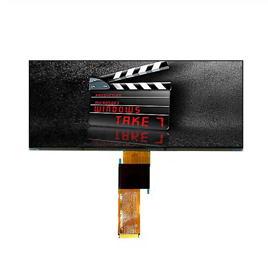
C123HAX04.U Reverse AHVA Bar Display Cell AUO
Model P/N
Size
Resolution
Brightness
Viewing Angle
Connector Type
Operating Temp
Overall(mm)
auo
C123HAX04.U
Brand
Panel Size (inch)
Model P/N
Resolution
Viewing Angle
Contrast Ratio
Response Time
Overall (mm)
Active Area (mm)
Refresh Rate
Display Colors
Panel Type
Connector Type
Surface Treatment
Operating Temp
Touchscreen Type
Storage Temp
Work Mode
Pixel Format
Input Voltage (V)
Touch Interface
Designed For
Product Details
Product Overview
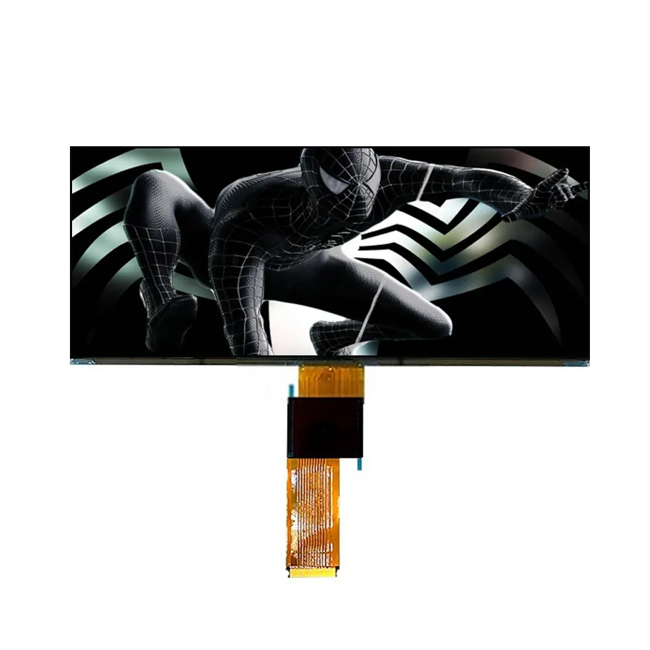
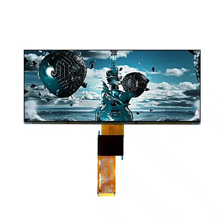
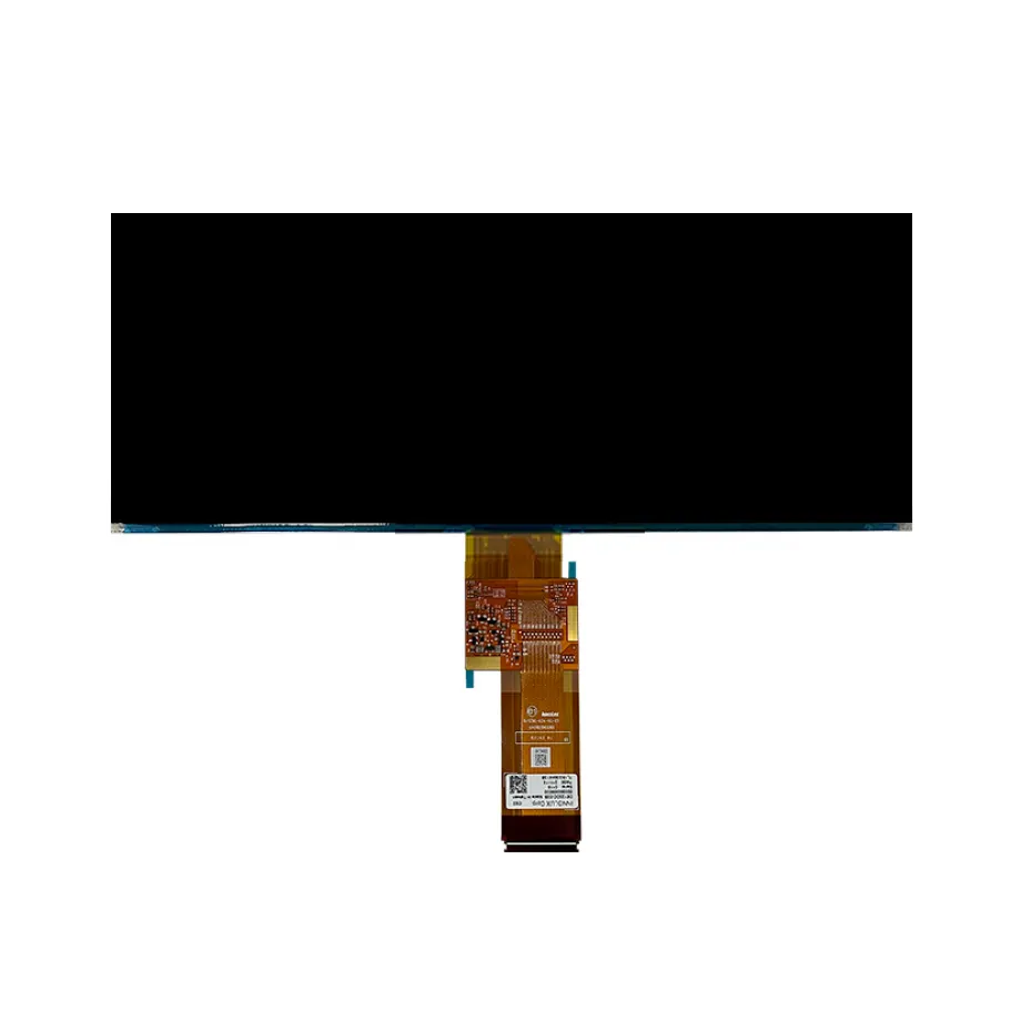
C123HAX04.U Reverse AHVA Bar Display Cell is a 12.3-inch AUO LTPS TFT-LCD FOB cell for Automotive Display integration. It uses a native 1920(RGB)×720 raster with an 8:3 bar format and a 292.032 × 109.512 mm active area. The cell outline is 297.03 × 118.84 × 0.65 mm, and the documented mass is 93.2 ± 0.9 g. AHVA normally-black transmissive operation is paired with 1400:1 typical contrast, 85/85/85/85 typical viewing-angle values at CR≥10, 16.7M colors with 70% NTSC wording and a hard-coated front surface with 5.5% maximum reflection.
This exact `.U` variant combines in-cell I²C touch, dual-channel 8-bit LVDS and a 60-pin 0.5 mm connector. It operates at 60 Hz from a 3.3 V typical input and includes U/D and L/R reverse-image feature wording. Transmissivity is 4.5% typical with polarizer. The response entry is a maximum Tr+Td time quantity with a numeric value of 25 and an incompatible length unit, so the engineering representation is 25 ms maximum without changing the number. Operating temperature is -30 to 85 °C and storage is -40 to 95 °C. As a bare cell, it requires an external backlight and does not itself provide a finished luminance value.
Three Core Buyer Value Propositions
1. A 60-pin, single-rail architecture can simplify the display-side integration target
Compared with wide automotive cells that expose numerous panel rails, this exact version is documented with a 3.3 V typical panel input and a 60-pin connector. That can simplify the system power concept and harness definition, while still requiring exact power sequencing, pin mapping and controller timing. The lower connector count should not be interpreted as compatibility with another 60-pin panel; LVDS pairs, touch signals, grounds and control assignments remain exact-model details.
2. Reverse-image capability supports flexible physical orientation when the system is designed for it
U/D and L/R reverse wording is useful when the mechanical package benefits from changing panel scan orientation or image direction. This can give the HMI designer more freedom around connector placement and physical mounting. The feature still needs controller and firmware verification because image reversal must align with touch coordinates, boot graphics and the intended user interface. It is not permission to rotate the cell arbitrarily without checking viewing, cable and mechanical constraints.
3. Known mass, reflection and 1400:1 contrast improve optical-mechanical planning
The 93.2 ± 0.9 g mass, 5.5% maximum surface reflection and 1400:1 typical contrast add useful controls that are not always available for bare FOG cells. Mechanical engineers can include an exact component mass in support calculations, while optical engineers can evaluate reflection and contrast as part of the cover/backlight stack. These remain panel-level specifications; finished sunlight readability, glare control and luminance require complete-system measurements.
Key Specifications at a Glance
| Parameter | Confirmed value |
|---|---|
| Manufacturer / model | AUO C123HAX04.U |
| Display size / format | 12.3 inch, 1920×720, 8:3 |
| Panel type | LTPS TFT-LCD, CELL (FOB) |
| Active area | 292.032 × 109.512 mm |
| Outline | 297.03 × 118.84 × 0.65 mm |
| Weight | 93.2 ± 0.9 g |
| Display mode | AHVA, Normally Black, Transmissive |
| Contrast ratio | 1400:1 typical |
| Viewing-angle values | 85/85/85/85 typical at CR≥10 |
| Response time | 25 ms maximum Tr+Td |
| Colors | 16.7M, 70% NTSC |
| Surface | Hard coating; reflection 5.5% maximum |
| Transmissivity | 4.5% typical with polarizer |
| Refresh rate | 60 Hz |
| Display interface | LVDS, 2 channels, 8-bit; 60-pin 0.5 mm connector |
| Touch | In-Cell Touch, I²C |
| Panel input | 3.3 V typical |
| Image direction feature | U/D, L/R reverse |
| Backlight | External; cell luminance 0 cd/m² |
| Operating / storage | -30 to 85 °C / -40 to 95 °C |
| Application | Automotive Display |
Why a 60-pin must be controlled separately
C123HAX04.U Reverse AHVA Bar Display Cell belongs to the same broad 12.3-inch bar-display space as other C123HAX04 variants, but its connector and power architecture are defining identity features. The uses a 60-pin 0.5 mm connector and a documented 3.3 V typical input. A visually similar sibling with a different suffix can expose more contacts or different supply requirements. Procurement should therefore record the complete suffix and reject substitutions that are justified only by diagonal, resolution or active area.
This distinction is particularly important in service and platform reuse. A cable may appear to mate physically yet carry different signal assignments, and a controller tuned for another variant can fail to initialize touch or image timing correctly. Build the BOM, incoming inspection and engineering-change process around C123HAX04.U itself. If a related panel is proposed, treat it as a new electrical and mechanical qualification rather than an automatic alternate.
How reverse-image functions should be integrated with touch coordinates
U/D and L/R reverse features can help when mechanical packaging favors a different scan orientation, but image direction and touch coordinates must remain synchronized. A controller or firmware change that flips the displayed image without remapping touch may create an obvious interaction error. Validation should include boot logo, operating-system orientation, edge gestures, touch targets near corners and any safety-relevant controls present in the HMI.
The reverse feature also does not eliminate the need to check the physical viewing direction. AHVA supports broad viewing angles, yet the complete optical stack and mounting angle can still influence perceived contrast and reflections. Before freezing panel orientation, test the production cover, polarizer direction, cable routing and HMI line of sight together. Use the reverse function as an integration option, not as a shortcut around mechanical validation.
Dual-channel LVDS remains the native image transport
Texas Instruments provides LVDS fundamentals and training that explain differential signaling, termination and noise considerations. For this panel, the exact native path is dual-channel 8-bit LVDS carrying the 1920×720/60 Hz image. System engineers should use the AUO pin map to identify pair ordering, clocking, grounds and non-LVDS control signals rather than relying on a generic two-channel wiring diagram.
The 60-pin connector also carries the rest of the cell's system connections, including touch/control functions as defined by the panel documentation. Automotive harness design should consider impedance, return paths, connector retention and EMI exposure. Test display stability during engine-start-like transients and noisy operating states on production-intent hardware. A successful room-temperature bench image is only an early milestone, not final interface qualification.
External backlight design starts from transmissivity, not from the 0-nit cell entry
The recorded 0 cd/m² value is appropriate for a bare cell because no backlight is integrated. The 4.5% typical transmissivity with polarizer is the more useful optical cell parameter for backlight planning. The final display must add a light source, optical films, mechanical carrier and thermal path capable of meeting the vehicle's day/night luminance range.
AUO's automotive display portfolio illustrates the breadth of in-vehicle display applications, but finished brightness targets depend on the specific cockpit location. A center display, cluster or passenger screen can face different ambient light and reflection requirements. Measure the assembled system through its cover lens and bonding stack rather than inferring finished luminance from a sibling module or portfolio example.
Reflection, hard coating and 1400:1 contrast are separate optical controls
The hard-coated surface is documented with 5.5% maximum reflection, while the LCD cell has a 1400:1 typical contrast ratio. These numbers describe different aspects of optical performance. Contrast is measured under specified panel conditions, while reflection describes how incident light interacts with the front surface. In a vehicle cabin, sunlight and bright trim can reduce perceived contrast even when the intrinsic cell ratio is high.
Optical validation should therefore include black and white states under controlled ambient illumination, angular viewing and the actual cover stack. Anti-reflection coatings or optical bonding added by the integrator can change the result and need their own measurements. Do not convert the 5.5% reflection limit into a claim of sunlight readability, and do not treat the 1400:1 ratio as an HDR certification.
Single 3.3 V input simplifies the record but does not remove sequencing checks
The exact model lists a 3.3 V typical panel input, which is much simpler to communicate than a multi-rail bare-cell architecture. The system still needs to respect power-on/off timing, reset behavior and any internal bias generation requirements specified by AUO. A stable 3.3 V rail at steady state does not prove a safe startup sequence. The ECU or display controller should be validated for repeated ignition cycles, brownouts and fast restart scenarios.
Because the cell also includes in-cell touch, power-state transitions should verify both image and touch recovery. Test sleep, wake, complete power removal and restart at hot and cold limits. Any current-consumption or inrush limits not present in the confirmed facts should be obtained from exact-model documentation rather than assumed from the `.K` sibling or another 12.3-inch AUO panel.
In-cell I²C touch is an integrated feature, not a generic compatibility promise
The touch function is built into the cell and uses I²C communication. Qualification should verify bus voltage, address, reset/interrupt behavior, coordinate mapping and touch recovery after display power-state changes. If the HMI requires multi-touch gestures, glove use or moisture performance, those are separate acceptance criteria that need exact supporting evidence or system tests; they are not implied merely by the “In-Cell Touch” label.
Touch performance must be evaluated after the cover lens, bonding process and grounding strategy are defined. Long vehicle harnesses and switching power electronics can introduce noise that is absent from a laboratory setup. EMI testing should include active touch use while the backlight and LVDS interface operate across brightness and image modes. This helps prevent false touches or intermittent communication from appearing late in the program.
Temperature and mechanical boundaries for a long, thin cell
The documented operating range is -30 to 85 °C and storage is -40 to 95 °C. These are component boundaries, not a declaration of an automotive qualification standard. Cold response, hot contrast and touch behavior should be checked at relevant extremes. The 25 ms maximum Tr+Td value is a panel transition specification under its test basis and should remain separate from complete HMI response time.
The cell is only 0.65 mm thick and approximately 297 mm wide, so mechanical support matters. Its 93.2 ± 0.9 g mass provides a useful input, but frame stiffness, bonding stress and connector loading can still dominate reliability. Design fixtures and housings to avoid localized pressure or torsion, particularly during temperature cycling. Use the exact drawing to establish support and keep-out zones before production tooling.
Application fit: wide interactive vehicle displays with orientation flexibility
C123HAX04.U Reverse AHVA Bar Display Cell is explicitly associated with Automotive Display use. Its wide 8:3 geometry can support center information, vehicle controls or other elongated cockpit layouts when the HMI is designed around the confirmed 1920×720 timing, external backlight and integrated touch. Reverse-image functionality adds another integration option when connector or mounting constraints favor a different orientation.
These are compatible design scenarios rather than named vehicle-fit claims. No OEM platform, safety integrity level, regulatory approval or exact dashboard assembly is established. The complete display system must still qualify its controller, backlight, housing, optical stack, EMC performance and environmental behavior. Treat the `.U` suffix as its own controlled component because the `.K` sibling differs in connector count, supply architecture, optical values and temperature boundary.
Procurement and validation checklist
- Lock AUO C123HAX04.U and the full `.U` suffix in purchasing and incoming inspection.
- Verify native 1920×720/60 Hz timing over dual-channel 8-bit LVDS.
- Confirm the 60-pin 0.5 mm connector and exact signal/touch mapping.
- Validate the 3.3 V input sequence through repeated power cycles and thermal extremes.
- Coordinate U/D and L/R reverse-image modes with touch-coordinate mapping and HMI orientation.
- Design the external backlight around 4.5% transmissivity and the target day/night luminance range.
- Measure reflection and contrast through the completed cover/bonding stack.
- Use the documented 93.2 ± 0.9 g mass and exact mechanical drawing for support design.
- Keep the 25 ms maximum Tr+Td response qualifier intact after unit-semantic correction.
- Do not infer an automotive certification, named vehicle fit or lifecycle guarantee from application wording.
For qualification of C123HAX04.U Reverse AHVA Bar Display Cell, provide the target vehicle HMI layout, LVDS controller, 60-pin cable design, 3.3 V power sequence, backlight and optical targets, touch requirements, mounting orientation and environmental limits. Exact-model control is the safest way to preserve the connector, reverse-image, optical and thermal behavior expected by the finished vehicle display.
Recommended: Same Size
(12.3")
Applications & Value of LCD Panel

- Fast sourcing with in-stock panels & cross-reference alternatives
- Stable supply chain with long-term availability
- Engineering-level support from panel to integration
- Custom solutions: cable, touch & optical bonding
- Strict quality control with IQC / OQC / aging test
- Full traceability system for quality assurance
- Complete technical documentation & drawings
- Compliance support: RoHS & certification files