
~
~
~
~
~
~
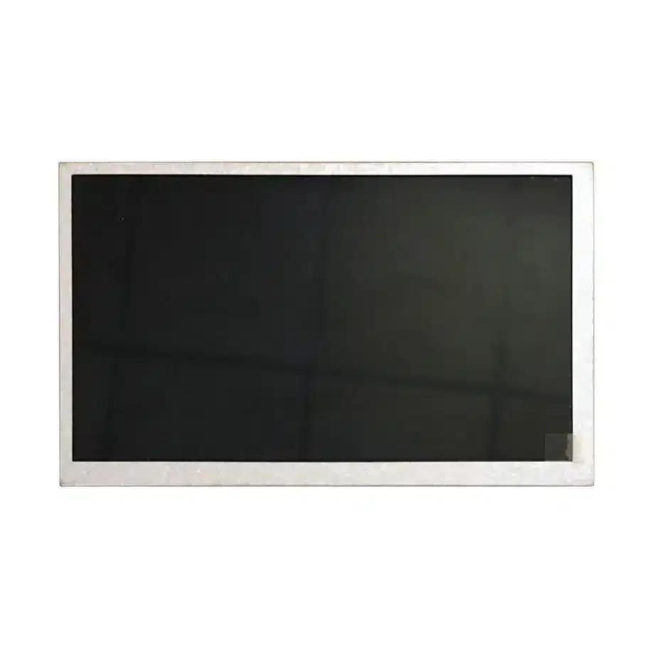
HSD080IDW1-A00 TTL WVGA TFT LCD Module 8 Inch TN HannStar
Model P/N
Size
Resolution
Brightness
Viewing Angle
Connector Type
Operating Temp
Overall(mm)
hannstar
HSD080IDW1-A00
Brand
Panel Size (inch)
Model P/N
Resolution
Brightness (nits)
Viewing Angle
Contrast Ratio
Response Time
Overall (mm)
Active Area (mm)
Refresh Rate
Display Colors
Panel Type
Connector Type
Surface Treatment
Operating Temp
Touchscreen Type
Storage Temp
Work Mode
Pixel Format
Input Voltage (V)
Vibration Resistance
Weight (g)
Designed For
Product Details
Product Overview
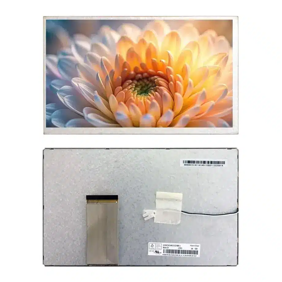
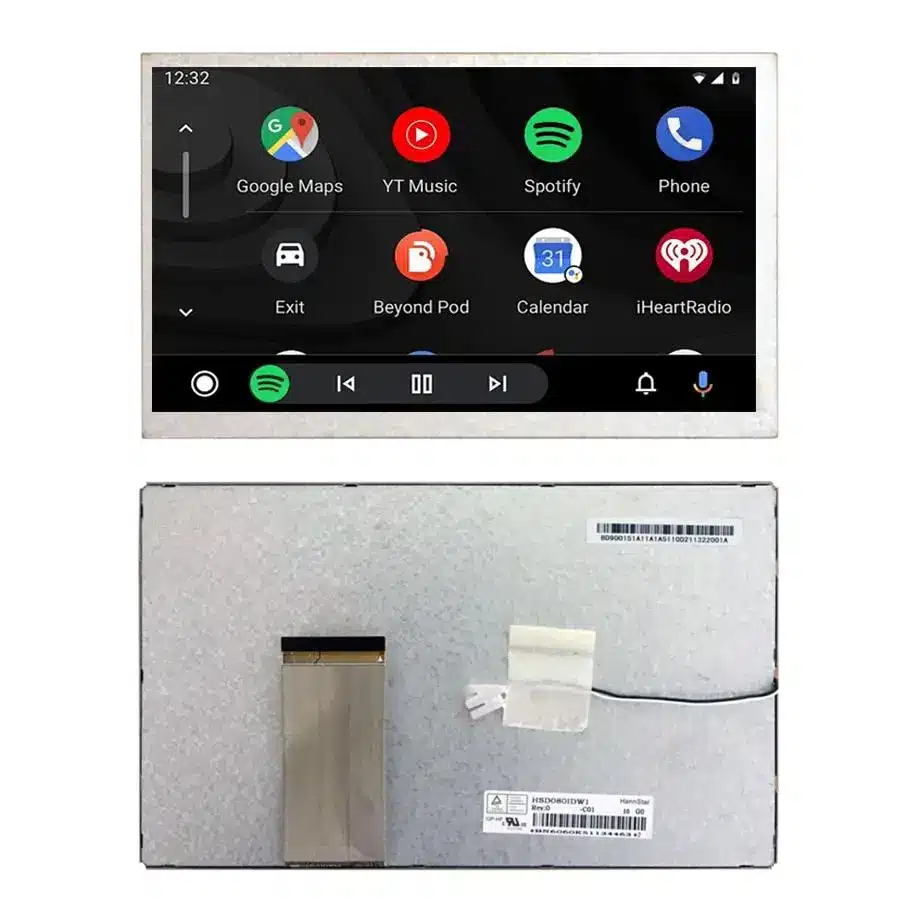
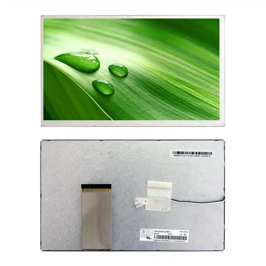
The HSD080IDW1-A00 TTL WVGA TFT LCD Module is an 8.0-inch HannStar display module for digital photo frames and portable DVD player integration. It combines an 800(RGB)×480 image format with a TN, normally white, transmissive panel and an integral WLED backlight. The native connection is TTL, one channel, 6/8-bit, through a 60-pin FPC. It is supplied without a touch screen and without a backlight driver.
For a replacement or new assembly, the main engineering decision is whether the host can support the complete panel arrangement: parallel video, the specified power rails, a separate LED-driving circuit and the physical cable route. Matching the diagonal alone does not establish compatibility. The typical luminance is 200 cd/m², so optical evaluation should start with the actual indoor lighting and intended viewing position.
Three Core Buyer Value Propositions
A defined TTL connection for host screening
The one-channel, 6/8-bit TTL interface and 60-pin FPC give electronics teams a concrete starting point for comparing an existing host output. This can identify unsuitable signal architectures before purchasing samples. A matching connector count is only an initial filter; the exact pin assignment, timing and electrical requirements must still agree.
Separate dimensions for the image and enclosure
The active area is 176.64×99.36 mm, while the module outline is 192.8×116.9×6.92 mm. These two measurements let mechanical teams assess the visible opening and housing clearance independently. Mounting details, tolerances and cable space still require the model drawing before a replacement can be approved.
Optical data that guides the viewing test
A 200 cd/m² typical brightness, antiglare surface and 6 o'clock best-view designation support a focused evaluation of a fixed viewing position in controlled lighting. The TN construction makes orientation an important selection issue. These attributes do not establish sunlight readability or equivalent image quality from every direction.
Key Specifications at a Glance
| Parameter | Specification |
|---|---|
| Model / manufacturer | HSD080IDW1-A00 / HannStar |
| Size and image format | 8.0 inch; 800(RGB)×480, WVGA, 16:9 |
| Active area / outline | 176.64×99.36 mm / 192.8×116.9×6.92 mm |
| Optics | 200 cd/m² typical; 500:1 typical contrast (TM); TN, normally white, transmissive |
| Viewing and response | 70/70/50/60 typical at CR≥10; 6 o'clock best view; 5/20 ms typical Tr/Td |
| Native interface | TTL, 1 channel, 6/8-bit; 60-pin FPC |
| Panel supplies | 3.0/10/15/-9 V typical, corresponding to VCC/AVDD/VGH/VGL |
| Backlight / touch | 3S6P WLED, no driver; without touch screen |
| Temperature | Operating: -20 to 70 °C; storage: -30 to 80 °C |
What Must the HSD080IDW1-A00 Host Electronics Provide?
The host must produce the correct panel-side TTL signal and support the associated power arrangement. This module is not a finished HDMI monitor. If the source equipment provides HDMI or another incompatible video output, a conversion design must be selected and qualified for the exact panel. No particular controller board is established as a matched accessory.
Keep video timing separate from connector fit
Obtain the pin table and timing specification before routing an adapter. Check how pixel data, clock, synchronization and control signals are assigned, then compare the host configuration with the panel documentation. Texas Instruments' display-subsystem documentation illustrates why parallel display outputs require appropriate timing and pixel-clock configuration. It is engineering context, not confirmation that a particular TI processor directly supports this module.
Treat each named supply as a separate requirement
The typical values are 3.0 V VCC, 10 V AVDD, 15 V VGH and -9 V VGL. A design review must retain all four rail names and polarities. Obtain their allowable ranges, current requirements and sequence from the panel documentation; do not select regulator ratings from typical voltages alone. A controller board's own input supply is a different specification and cannot replace this panel-rail list.
How Does the 60-Pin FPC Affect Replacement Approval?
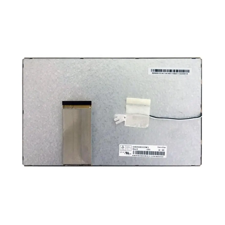
FPC compatibility involves its geometry and contact arrangement as well as the pin count. Compare the mating connector, cable exit, contact side, available bend space and retention method. A cable that physically enters a socket may still connect the wrong electrical functions. Record the exact panel suffix and the existing assembly photographs before choosing an adapter route.
Check the visible opening before changing the housing
The HSD080IDW1-A00 TTL WVGA TFT LCD Module has a 176.64×99.36 mm active area inside a larger 192.8×116.9 mm outline. A bezel must expose the intended image without pressing on the display surface or obscuring edge content. Use the 6.92 mm thickness for initial clearance screening, then check the complete drawing for local features and tolerances. Leave room for the actual FPC path and mating hardware rather than treating the outline as the whole assembly envelope.
The 240 g typical module weight is also relevant to support and handling. It does not define the load capacity of a bracket or adhesive. Qualify the mounting arrangement in the intended equipment, especially where a portable player hinge or repeated handling can transfer force to the panel connection.
Where Should an 8-Inch TN Screen Be Viewed?
Start the optical test at the intended user's position, with the panel installed in its final orientation. The best-view designation is 6 o'clock, and the viewing-angle values are 70/70/50/60 typical at a contrast-ratio threshold of CR≥10. These figures are not assigned to individual directions here because that order needs the model documentation. Rotating the assembly changes the relationship between the viewer and the panel.
Evaluate actual images and menus
Photo frames should be checked with skin tones, dark scenes and bright backgrounds; portable DVD layouts should include subtitles and menu text. Test the finished front stack at the planned viewing distance and angle. The display supports 262K/16.2M colors, but that notation alone does not establish which host mode produces each result or a particular color-gamut specification. Confirm the selected interface mode during image approval.
The 500:1 typical contrast and antiglare, 3H hard-coated surface are useful selection attributes. Added front glass or a protective layer can change reflections and apparent contrast. The 200 cd/m² typical luminance should therefore be assessed through the complete front assembly, with room lighting representative of deployment. Do not treat the hard-coating designation as proof of cover-glass impact resistance.
Why Does the WLED Backlight Need Its Own Review?
The module incorporates a 3S6P WLED backlight but no backlight driver. The electronics design must therefore provide an appropriate LED-driving circuit in addition to the panel's video and supply arrangement. Obtain the backlight electrical specification before selecting output current, voltage capability or control behavior. The topology label alone does not supply those operating values.
The Texas Instruments backlight-driver overview identifies current, voltage drop and dimming as practical driver-selection considerations. For this HannStar module, the driver choice remains a project-specific engineering decision. There is no confirmed dimming method, brightness-control range or approved driver IC in the module details used here.
Define what the sample must demonstrate
Measure the optical result at the intended LED operating point, inspect uniformity and observe behavior during startup and sustained use. If brightness control is required, include the proposed control circuit in the sample build. The listed backlight life is 20,000 hours, but the test conditions and end-of-life criterion are not established here. Qualification should identify those conditions before using that figure in a service-life calculation.
What Environmental Limits Apply to HSD080IDW1-A00?
The operating range is -20 to 70 °C, and the storage range is -30 to 80 °C. Operation and storage are different states: a storage limit is not permission to run the display at that temperature. Assess the panel's local temperature inside the equipment, including heat from the backlight-driving and host electronics.
The listed vibration value is 2.9G, or 28.4 m/s². Without the associated frequency, duration and mounting conditions, it cannot establish compliance with a complete equipment vibration requirement. Likewise, temperature limits do not prove automotive, medical or transportation qualification. For portable use, compare the actual handling and environmental requirements with the complete model test documentation.
Photo-Frame and Portable DVD Integration Decisions
The confirmed applications are digital photo frames and portable DVD players. Both require attention to image presentation and the physical viewing arrangement. For a frame, consider whether the housing angle places the main viewer near the preferred direction. For a player, assess the display at the practical hinge positions rather than approving only a flat bench sample.
When evaluating the HSD080IDW1-A00 TTL WVGA TFT LCD Module, retain its native 800×480 pixel dimensions in the host configuration. Check scaling, text placement and image proportions with representative content. A native pixel count does not, by itself, define every timing setting or prove that an existing firmware configuration is suitable.
The standard module is non-touch. Any proposed touch layer, cover glass or bonded assembly requires a separate feasibility review covering optics, mechanics and the additional electronics. Those additions should not be described as included features or available custom configurations until the actual project has been evaluated.
Procurement Checklist Before Sample Approval
- Specify HannStar HSD080IDW1-A00 and confirm the exact suffix on the offered module.
- Request the current pin assignment, timing information, mechanical drawing and backlight electrical details.
- Compare the 60-pin FPC arrangement and all four named panel supplies with the host design.
- Confirm the separate LED-driving circuit and its qualification plan.
- Check active-area alignment, module clearance, cable routing and mounting support.
- Define acceptable image behavior at the intended viewing positions and room lighting.
- Ask for current quantity, condition, traceability and delivery information for the specific order.
A sourcing decision for the HSD080IDW1-A00 TTL WVGA TFT LCD Module should be tied to an approved sample configuration. Record the host, cable, power design, backlight circuit and optical stack used in that approval. Current stock, future availability and any change-notification arrangements require separate confirmation; the technical specification is not a supply-duration commitment.
Recommended: Same Size
(8")
Applications & Value of LCD Panel

- Fast sourcing with in-stock panels & cross-reference alternatives
- Stable supply chain with long-term availability
- Engineering-level support from panel to integration
- Custom solutions: cable, touch & optical bonding
- Strict quality control with IQC / OQC / aging test
- Full traceability system for quality assurance
- Complete technical documentation & drawings
- Compliance support: RoHS & certification files
