~
~
~
~
~
~
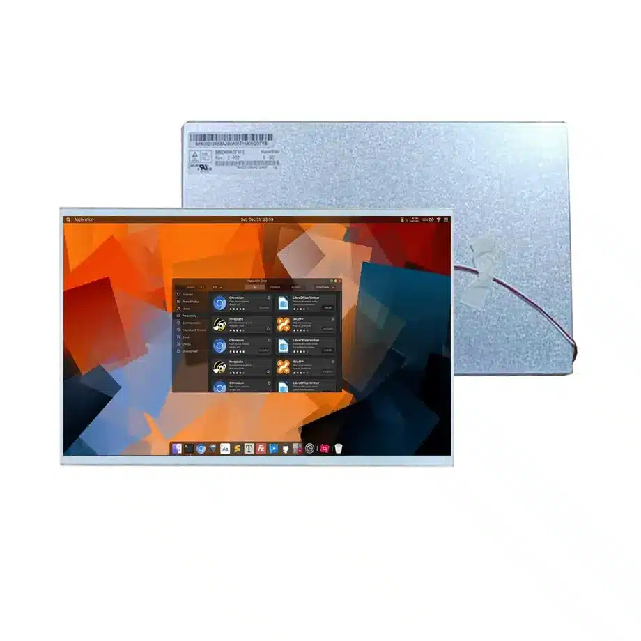
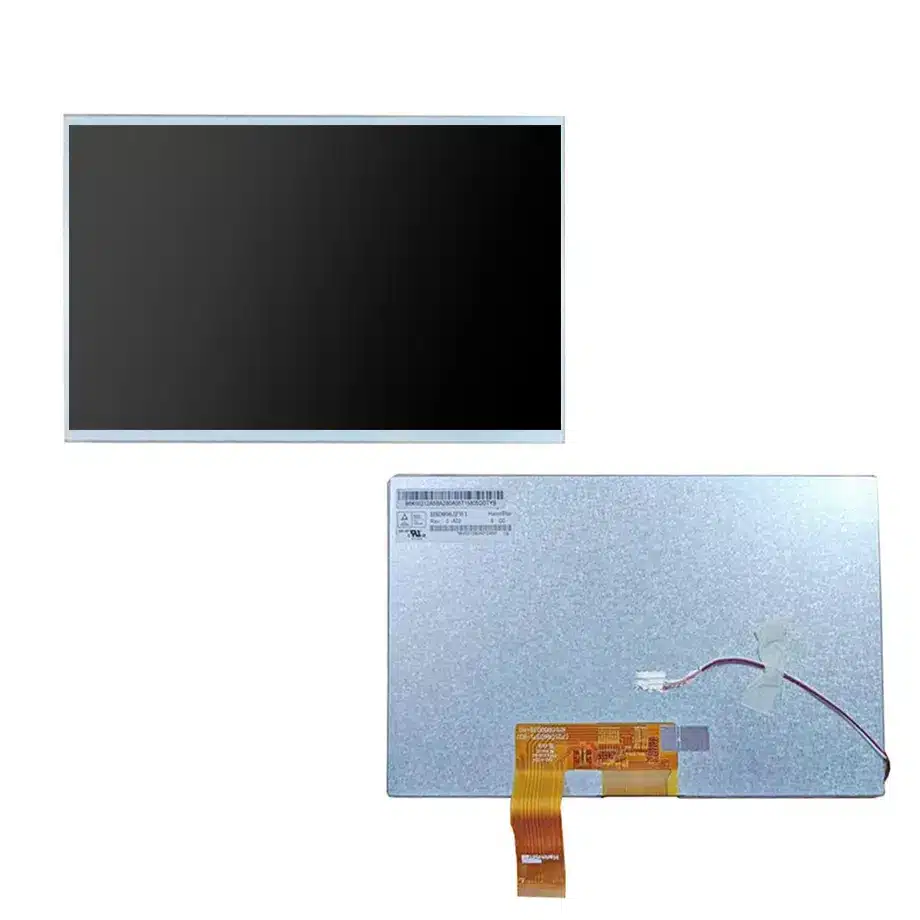
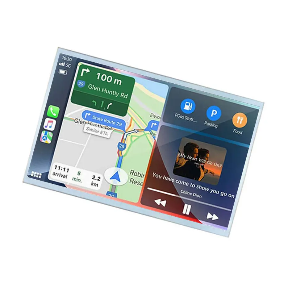
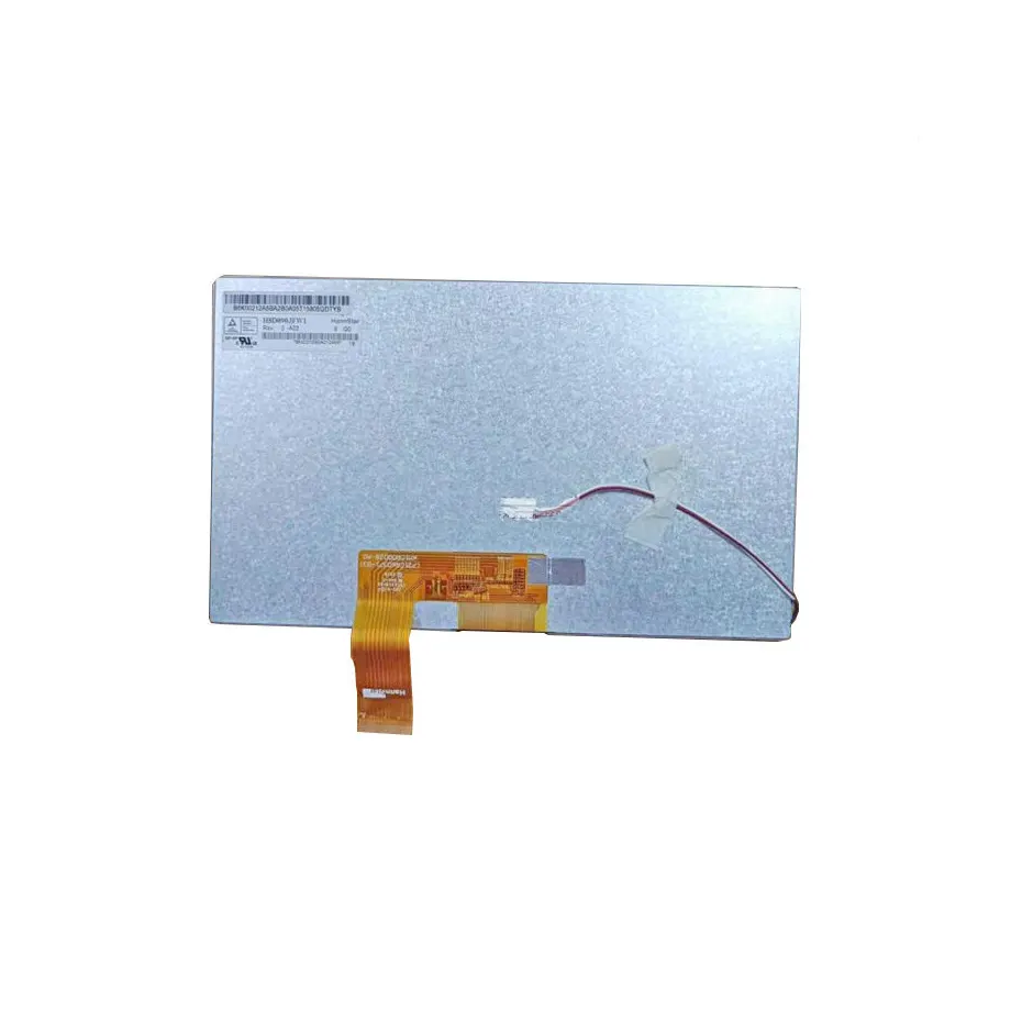
HSD090JFW1-A03 3G-Vibration Automotive Display Module
Model P/N
Size
Resolution
Brightness
Viewing Angle
Connector Type
Operating Temp
Overall(mm)
hannstar
HSD090JFW1-A03
Brand
Panel Size (inch)
Model P/N
Resolution
Brightness (nits)
Viewing Angle
Contrast Ratio
Response Time
Overall (mm)
Active Area (mm)
Refresh Rate
Display Colors
Panel Type
Connector Type
Surface Treatment
Operating Temp
Touchscreen Type
Storage Temp
Work Mode
Pixel Format
Input Voltage (V)
Vibration Resistance
Weight (g)
Designed For
Product Details
HSD090JFW1-A03 3G-Vibration Automotive Display Module is a 9.0-inch HannStar a-Si TFT-LCD module documented for Industrial and Automotive Display applications. The exact-model parameter set combines 1024×600 WSVGA resolution, 500 cd/m² typical luminance, IPS Pro normally-black transmissive operation, 60 Hz refresh and a one-channel 8-bit LVDS interface through a 40-pin FPC. The active area is 196.608 × 114.15 mm within a 211.1 × 126.5 × 7.1 mm outline, with a typical mass of 226 g. The module is specified for -20 to 70°C operation, -30 to 80°C storage and 2.9G vibration, while the 3S13P WLED backlight is supplied without a driver.
Application evidence: industrial and in-vehicle display integration
The user-supplied exact-model record explicitly lists Industrial and Automotive Display. That supports evaluation for equipment HMIs and vehicle display systems when the electrical, mechanical and environmental limits match the target program. The taxonomy classification does not itself prove automotive qualification, AEC status, functional-safety compliance or any named OEM approval. Those system and certification requirements must be established separately by the finished product program.
The wide operating window and documented vibration value are useful engineering facts because they extend beyond typical office-panel conditions. They should still be interpreted as component limits, not as a complete ruggedness claim. Enclosure vibration, mounting resonance, thermal gradients, connector retention and system-level EMC can determine whether the finished display survives its real environment.
Three Core Buyer Value Propositions
1. -20 to 70°C operation gives designers a verified wide-temperature component window
The panel's operating range supports applications that may experience colder starts or hotter enclosure conditions than conventional indoor displays. This is particularly relevant to industrial cabinets and vehicle interiors. The correct engineering approach is to use the -20 to 70°C range as a component boundary and then measure the actual panel temperature in the final enclosure. Solar load, heater use, processor heat and ventilation can move the local LCD temperature away from ambient.
2. 2.9G vibration data supports mechanical screening for mobile equipment
The source lists a maximum vibration level of 2.9G (28.4 m/s²), often summarized as a 3G-vibration feature. That provides more specific screening information than a generic “rugged” label. It does not establish compliance to a particular automotive or industrial vibration standard because no test method, axis profile or certification is asserted in the current evidence. Mechanical engineers should compare the actual application profile with the exact HannStar test conditions before approving the part.
3. 500-nit IPS Pro optics and LVDS simplify mainstream embedded display architecture
The module combines 500 cd/m² typical luminance, 800:1 typical contrast and wide viewing angles with a familiar one-channel LVDS interface. This gives embedded controller teams a practical integration target. The WLED system has no driver, so the host design must still provide appropriate LED drive and dimming. Final visibility under bright outdoor or vehicle conditions depends on the front stack and ambient reflections; 500 nits alone is not a sunlight-readable certification.
Key Specifications at a Glance
| Specification | HSD090JFW1-A03 value |
|---|---|
| Display size | 9.0 inch |
| Panel type | a-Si TFT-LCD, LCM |
| Resolution | 1024×600 WSVGA, 17:10 |
| Active area | 196.608 × 114.15 mm |
| Outline | 211.1 × 126.5 × 7.1 mm |
| Weight | 226 g typical |
| Brightness | 500 cd/m² typical |
| Contrast | 800:1 typical |
| Viewing angle | 85/85/85/85 typical at CR≥10 |
| Response | 17/18 typical Tr/Td |
| Colors | 16.2M, 50% NTSC |
| Refresh rate | 60 Hz |
| Interface | LVDS 1 ch, 8-bit, 40-pin FPC |
| Supply rails | 3.3 / 12.5 / 23 / -10 V typical (VDD / AVDD / VGH / VGL) |
| Backlight | 3S13P WLED, 15K hours, no driver |
| Operating / storage | -20 to 70°C / -30 to 80°C |
| Vibration | 2.9G (28.4 m/s²) |
Temperature qualification should use the local panel environment
A component limit is most useful when the actual application temperature is measured at the component. For industrial equipment, enclosure sealing, processor load and fan strategy can raise the LCD temperature. For a vehicle display, solar heating and parked-cabin conditions can create a different thermal profile from the outside air. The design team should map those conditions to the panel's -20 to 70°C operating range and maintain margin rather than assuming ambient temperature equals panel temperature.
HSD090JFW1-A03 3G-Vibration Automotive Display Module should be tested at the cold and hot ends relevant to the product. Verify startup, image stability, backlight behavior, response and visible artifacts after temperature soak. The source provides storage limits down to -30°C and up to 80°C, but storage survival is not the same as powered operation.
Vibration and mounting design are coupled
The 2.9G component vibration figure is meaningful only when the finished mounting method avoids amplifying stress. Brackets, bezels, foam supports and cable retention can change the mechanical load seen by the module. Prototype assemblies should be checked for connector fretting, frame resonance, glass pressure and visible image disturbance under the program's actual vibration profile.
The 211.1 × 126.5 × 7.1 mm outline and 226 g typical mass give the mechanical team a defined starting envelope. Use the exact drawing for mounting points and keep-out areas. Do not infer bracket locations or fastening torque from another HSD090JFW1 revision even if the external dimensions appear similar.
LVDS, multi-rail power and backlight-driver responsibilities
The display signal is one-channel 8-bit LVDS over a 40-pin FPC. The module also lists multiple supply rails: 3.3 V VDD, 12.5 V AVDD, 23 V VGH and -10 V VGL. These values describe the panel architecture but do not replace the exact sequencing and current requirements in the manufacturer specification. Power-up/down timing, reset behavior and fault protection should be reviewed before PCB release.
The backlight is a 3S13P WLED system without a driver. The host therefore needs an appropriate constant-current LED driver and dimming strategy. Confirm LED current and voltage requirements from the exact model documentation. The listed 15K-hour light-source reference should remain a component specification, not a finished-equipment service-life guarantee.
Optical performance in industrial and vehicle environments
The 500 cd/m² typical luminance and antiglare 3H surface provide useful brightness and reflection control for many embedded displays. They do not prove sunlight readability. Vehicle cockpits and outdoor industrial equipment can present much higher ambient illumination than a laboratory. Front glass reflectance, air gap or optical bonding, polarizer orientation and display angle can materially affect perceived contrast.
If the application requires direct-sun visibility, measure the complete stack under the specified ambient condition. The current evidence does not provide a supported sunlight-readable classification, so the product page avoids that claim. Similarly, 50% NTSC describes the supplied color-gamut reference but does not establish a calibrated system color standard.
Automotive use does not equal automotive certification
Automotive Display appears in the exact application evidence, which is sufficient for the product's application taxonomy and for engineering evaluation in vehicle display systems. It is not sufficient to claim ISO 26262 compliance, AEC qualification, OEM approval, long-term vehicle supply or a particular change-notification process. Those commercial and compliance requirements need direct program evidence.
For a vehicle project, the system team should also validate EMC, power transients, dimming behavior, night-mode readability and thermal cycling at the finished-display level. The LCD module is one component within that system.
Industrial HMI integration boundaries
Industrial use can include machine controls, instrumentation and other embedded HMI equipment, but exact controller, enclosure and environmental requirements vary widely. The module has no touch screen, so an interactive HMI would require a separately engineered touch sensor. Adding a touch layer changes reflectance, luminance, thickness and mechanical loading, and the completed stack must be requalified.
The wide temperature range is useful but should not be converted into a blanket “industrial grade” certification. Procurement and engineering should reference the exact model's documented limits and the target equipment's own acceptance criteria.
Incoming inspection and change control
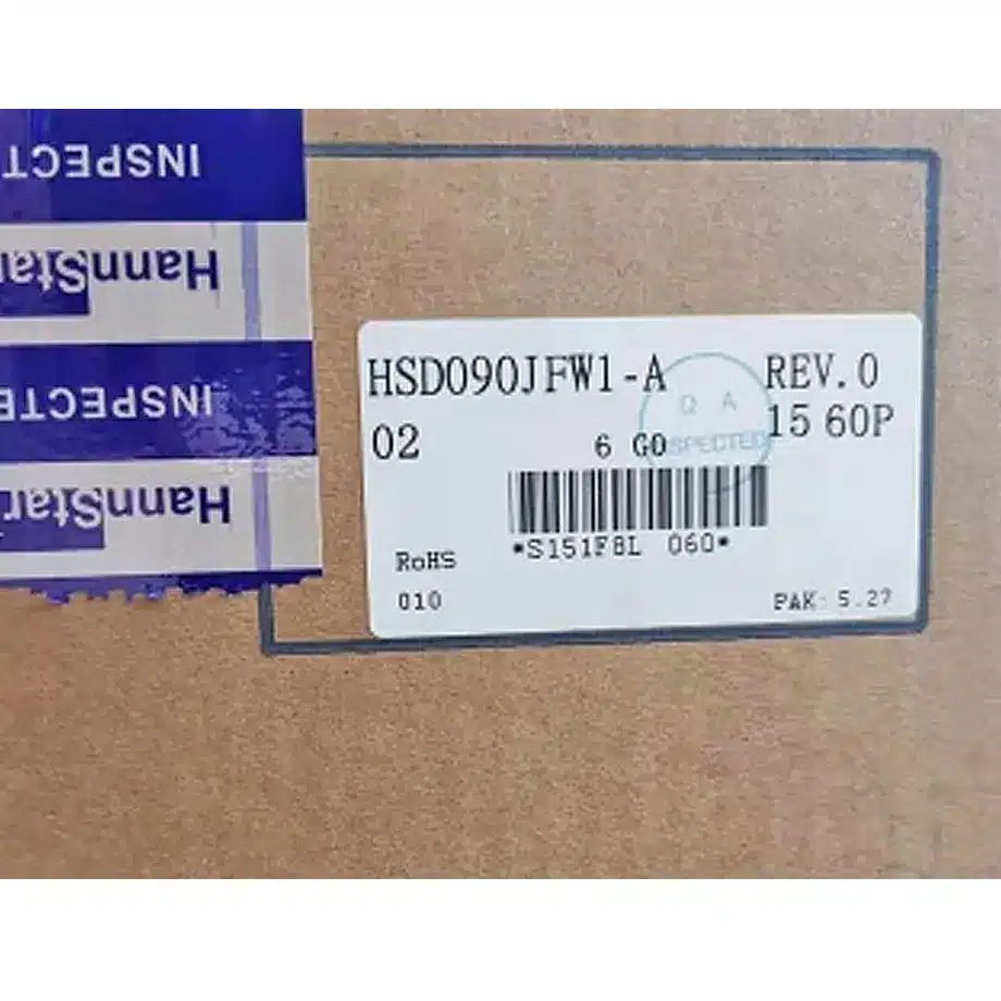
Confirm HSD090JFW1-A03 on the label, not merely the HSD090JFW1 family. Record the module revision, LVDS cable/FPC, backlight-driver design and mechanical drawing with the approved sample. Series revisions can share headline size and resolution while differing in details that matter to production.
HSD090JFW1-A03 3G-Vibration Automotive Display Module should enter the approved BOM only after temperature, vibration, optical, power and interface checks pass on the real system. Keep test limits and firmware together with the sourcing record so later substitutions trigger controlled requalification rather than informal equivalence.
System validation sequence for harsh-environment projects
A useful qualification sequence is to establish room-temperature electrical operation first, then verify the backlight driver and dimming path, followed by temperature and vibration testing on the assembled system. This order helps isolate root causes if a failure appears under stress. Record any image artifact, startup delay, connector issue or touch-overlay interaction against the exact test condition. For vehicle or industrial programs with formal standards, map those program tests separately to the component limits instead of treating the panel's temperature and vibration figures as a substitute for system compliance evidence.
Engineering summary
HSD090JFW1-A03 3G-Vibration Automotive Display Module is a 9-inch 1024×600 IPS Pro module with 500-nit luminance, one-channel LVDS, a separate WLED-driver requirement, -20 to 70°C operation and a documented 2.9G vibration level. Its strongest value is the combination of embedded-display optics and environmental data for Industrial and Automotive Display applications. Those component facts support qualification planning while leaving vehicle certification, rugged compliance and system-level reliability to the finished product program.
Recommended: Same Size
(9")
Applications & Value of LCD Panel

- Fast sourcing with in-stock panels & cross-reference alternatives
- Stable supply chain with long-term availability
- Engineering-level support from panel to integration
- Custom solutions: cable, touch & optical bonding
- Strict quality control with IQC / OQC / aging test
- Full traceability system for quality assurance
- Complete technical documentation & drawings
- Compliance support: RoHS & certification files