Freya Yang
+86 18318948097
+852 62667476
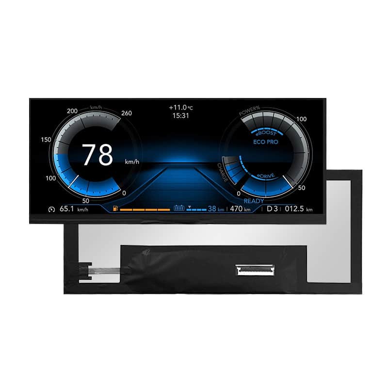
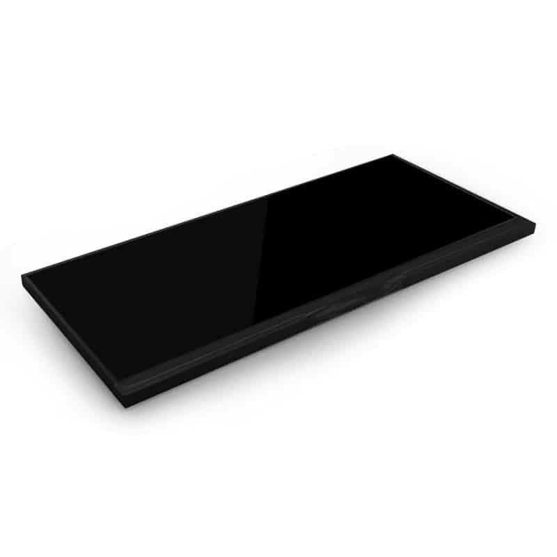
10.25 Inch Panoramic LVDS LCD Module Bar Display for Dashboard HMIs



Model P/N
Size
Resolution
Brightness
Viewing Angle
Connector Type
Operating Temp
Overall(mm)
huisoar
HS103Z7M-K10-50
Brand
Panel Size (inch)
Model P/N
Resolution
Brightness (nits)
Viewing Angle
Contrast Ratio
Response Time
Overall (mm)
Active Area (mm)
Refresh Rate
Display Colors
Panel Type
Connector Type
Surface Treatment
Operating Temp
Touchscreen Type
Storage Temp
Work Mode
Pixel Format
Control Type
Operating Environment
Designed For
10.25 Inch Panoramic LVDS LCD Module Bar Display for Dashboard HMIs
This ultra-wide IPS module combines a native 1920 × 720 canvas, 1000-nit luminance and wide-temperature operation for dashboard-style embedded interfaces.
Product Summary
The Panoramic LVDS LCD Module Bar Display provides a wide, shallow display format for dashboard HMIs, equipment-status panels and embedded interfaces that cannot accommodate a conventional 16:9 screen. Its 1920 × 720 resolution supports detailed horizontal layouts while the 243.648 × 91.368 mm active area keeps the visible display region compact.
The panel combines IPS technology, normally black operation, 1000-nit luminance, 16.7M colors and 70% NTSC minimum gamut. LVDS provides the native display signal path, while the standard configuration remains non-touch unless a separate touch assembly is developed for the project.
Key Specifications
| Parameter | Value |
|---|---|
| Size | 10.25 inch |
| Resolution | 1920 × 720 pixels |
| Panel technology | IPS TFT LCD |
| Display mode | Normally black |
| Interface | LVDS |
| Luminance | 1000 nits |
| Active area | 243.648 × 91.368 mm |
| Pixel pitch | 0.1269 × 0.1269 mm |
| Pixel arrangement | RGB vertical stripe |
| Display colors | 16.7M |
| Color gamut | 70% NTSC minimum |
| Surface | HC with 3H hardness |
| Operating temperature | −30°C to +85°C |
| Storage temperature | −40°C to +95°C |
| Touch | Non-touch |
Native 1920 × 720 Panoramic UI Design
Dashboard and Status-Information Layouts
The ultra-wide raster supports information that naturally extends across a horizontal interface. Suitable UI structures include:
- instrument and status zones
- navigation or route information
- warning and notification bands
- equipment operating data
- media and communication information
- multi-zone machine dashboards
- panoramic smart-terminal interfaces
The format allows several data groups to remain visible without using the vertical space required by a conventional monitor.
Native-Raster Content Preparation
The 1920 × 720 raster should be driven natively to preserve panoramic UI detail.
Text, icons, curves and status graphics should be designed around the actual aspect ratio instead of being cropped from a 1920 × 1080 interface. Critical information must also remain inside the approved visible opening after bezel overlap and installation tolerances are applied.
1000-Nit IPS Optical Performance
Luminance Through the Finished Optical Stack
The LCD is specified at 1000 nits. This supports brighter embedded environments and dashboard-style assemblies where ambient light can exceed normal indoor-office conditions.
A 1000-nit panel does not by itself establish sunlight readability after cover glass, bonding, dimming and thermal conditions are applied.
Protective glass, touch sensors, air gaps, optical adhesive, surface reflections and installation angle can change final luminance and contrast. Finished-system testing should use the intended optical stack and operating environment.
Normally Black Mode and Color Gamut
Normally black operation supports a dark inactive appearance and can suit modern dashboard interfaces built around dark backgrounds and illuminated status elements.
The panel provides 16.7M colors and a 70% NTSC minimum gamut specification. This is relevant where colored warnings, maps, interface zones or branded graphics require more controlled color reproduction than a basic low-gamut panel.
The HC surface and 3H hardness provide a defined front-surface treatment, but they do not replace protective cover glass where impact or vandal resistance is required.
LVDS Host Integration
Timing, Mapping and Connector Qualification
An LVDS interface name does not guarantee timing, voltage, bit-width, connector or pin compatibility with an existing controller.
Before selecting a host board or releasing a display cable, confirm:
- native 1920 × 720 timing
- LVDS mapping
- signal voltage
- channel count
- bit width
- complete connector pinout
- connector position and orientation
- panel power requirements
- backlight power and dimming requirements
- cable length and routing
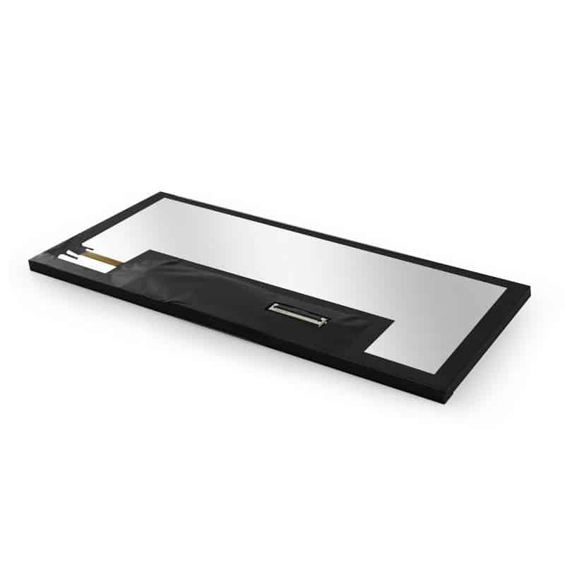
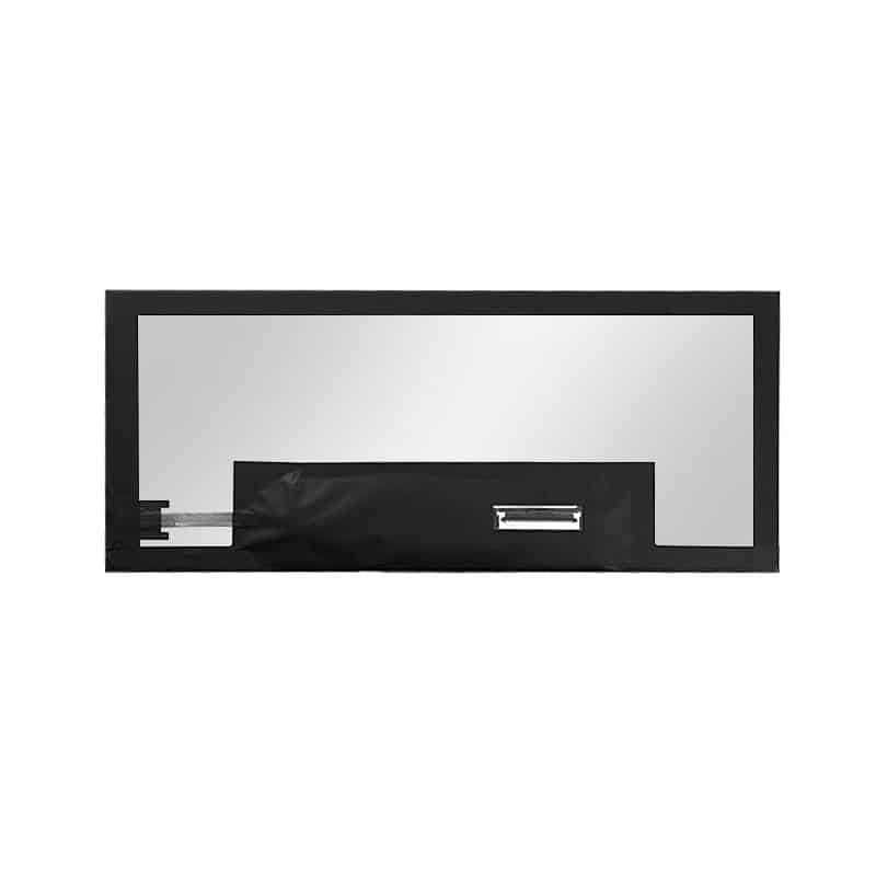
The connector shown in the mechanical material should not be assigned a pin count or electrical definition without the approved interface specification.
Non-LVDS Hosts Require a Controller Path
HDMI, DisplayPort, eDP, MIPI DSI, USB and parallel RGB sources cannot drive the module directly unless an appropriate bridge or controller generates the required LVDS output.
Controller-board qualification should cover:
- input format
- output timing
- scaling behavior
- LVDS mapping
- panel power
- backlight control
- startup behavior
- cable routing
- thermal conditions
Resolution alone does not establish compatibility.
Panoramic LVDS LCD Module Bar Display Mechanical Integration
Active Area and Visible Opening
The active display area is 243.648 × 91.368 mm. This value should control the image window, UI-safe area and front-glass opening.
The final bezel design should account for:
- active-area position
- border overlap
- assembly tolerances
- installation angle
- connector and cable clearance
- PCBA configuration
- front-glass printing
- mounting support
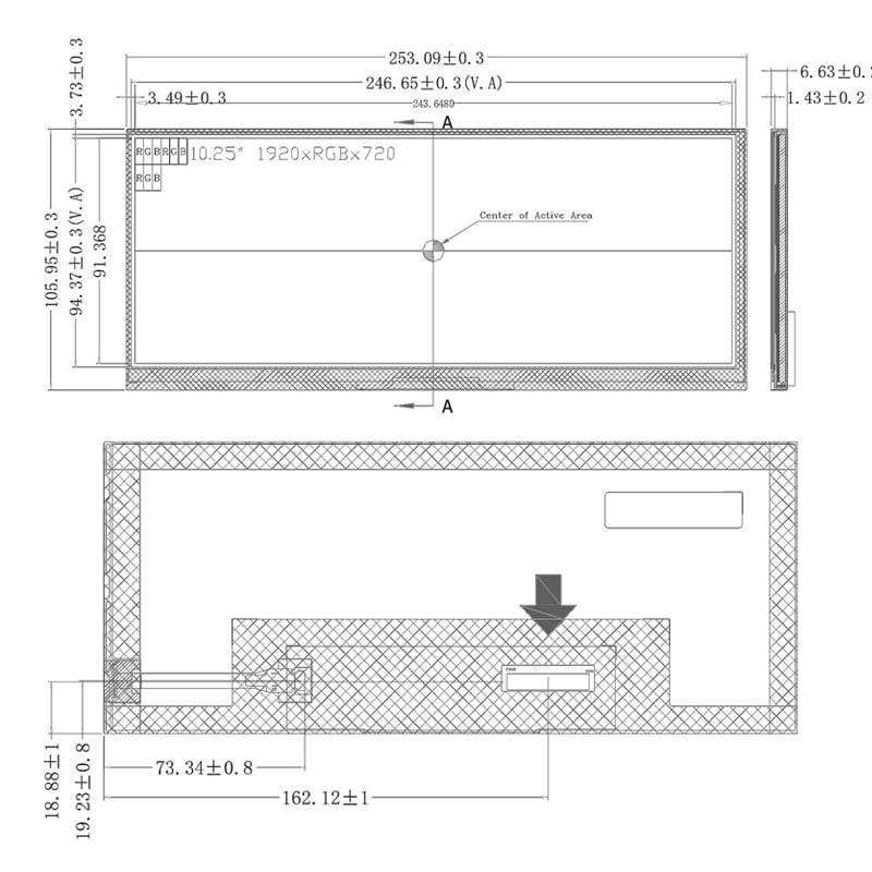
PCBA Variants and Drawing Conflicts
The specification table identifies separate mechanical variants:
- Without PCBA: 251.148 × 101.098 × 1.08 mm
- With PCBA: 251.148 × 142.548 × 3.2 mm maximum
The displayed mechanical drawing contains different envelope references, including a larger width, height and thickness. These values must not be treated as interchangeable.
The approved drawing for the ordered configuration must control:
- overall outline
- module thickness
- PCBA position
- connector location
- cable exit
- mounting geometry
- enclosure clearance
Tooling should not be released from the marketplace drawing alone.
Temperature and Application Boundaries
The module is specified for:
- operating temperature: −30°C to +85°C
- storage temperature: −40°C to +95°C
These ranges support evaluation for wider-temperature equipment than ordinary indoor commercial panels. They do not independently establish automotive, rail, marine, medical or other regulated-equipment qualification.
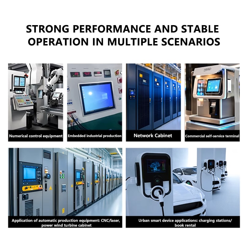
Potential applications include:
- dashboard-style HMIs
- industrial equipment dashboards
- panoramic control panels
- wide-format smart terminals
- transport-information interfaces after qualification
- embedded monitoring systems
- specialized multimedia interfaces
System approval still requires validation of vibration, thermal cycling, EMC, ESD, optical performance and certification requirements where applicable.
Non-Touch and Custom Integration Options
The standard LCD module is non-touch. It can be used where input is provided through:
- buttons
- rotary controls
- steering or remote controls
- external keypads
- centralized software
- a separately designed touch assembly
Project evaluation may include:
- LVDS controller-board matching
- cable and connector definition
- PCBA configuration
- cover glass
- HC or alternative surface review
- optical bonding
- enclosure adaptation
- mounting support
- brightness and dimming review
- touch-panel development
- graphics and logo printing
Custom configurations are generally reviewed from 500 pieces, subject to tooling requirements, material availability and the requested specification. Sample and standard-module quantities are confirmed separately.
Procurement Checklist
Before requesting sample or production approval, confirm:
- native 1920 × 720 timing
- LVDS channel and bit configuration
- signal voltage and mapping
- complete connector pinout
- connector orientation and position
- panel and backlight power requirements
- controller-board model
- with-PCBA or without-PCBA configuration
- approved mechanical drawing
- active-area and visible-opening position
- cover-glass or touch stack
- 1000-nit optical target
- operating and storage conditions
- sample quantity
- annual demand
- certification requirements
Sample approval should precede cable production, controller release, cover-glass tooling and enclosure manufacture.
FAQ
About 10.25 Inch Panoramic LVDS LCD Module Bar Display
What must be checked before connecting an LVDS controller?
How should panoramic 1920 × 720 content be prepared?
Does 1000-nit luminance establish sunlight readability?
Which mechanical dimensions should control enclosure release?
What must be confirmed before adding touch?
Freya Yang
+86 18318948097