Freya Yang
+86 18318948097
+852 62667476
13.3 Inch Embedded eDP Display Module for Touch HMI Consoles
Model P/N
Size
Resolution
Brightness
Viewing Angle
Connector Type
Operating Temp
Overall(mm)
huisoar
HS133FHP-300-30-V1
Brand
Panel Size (inch)
Model P/N
Resolution
Brightness (nits)
Viewing Angle
Response Time
Overall (mm)
Active Area (mm)
Refresh Rate
Display Colors
Panel Type
Connector Type
Surface Treatment
Operating Temp
Touchscreen Type
Storage Temp
Work Mode
Pixel Format
Control Type
Product Appearance Size
Protective Glass Specification
Operating Environment
I/O Interface
Designed For
13.3 Inch Embedded eDP Display Module for Touch HMI Consoles
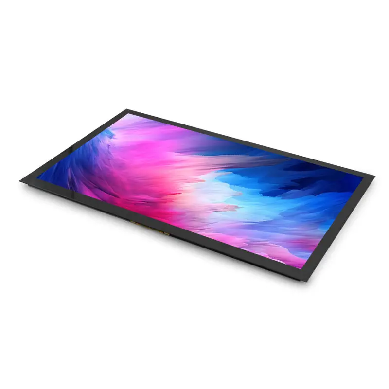
A Full HD 30-pin eDP panel with IPS-type imaging and a project-defined G+G capacitive-touch assembly for compact equipment interfaces.
Product Summary
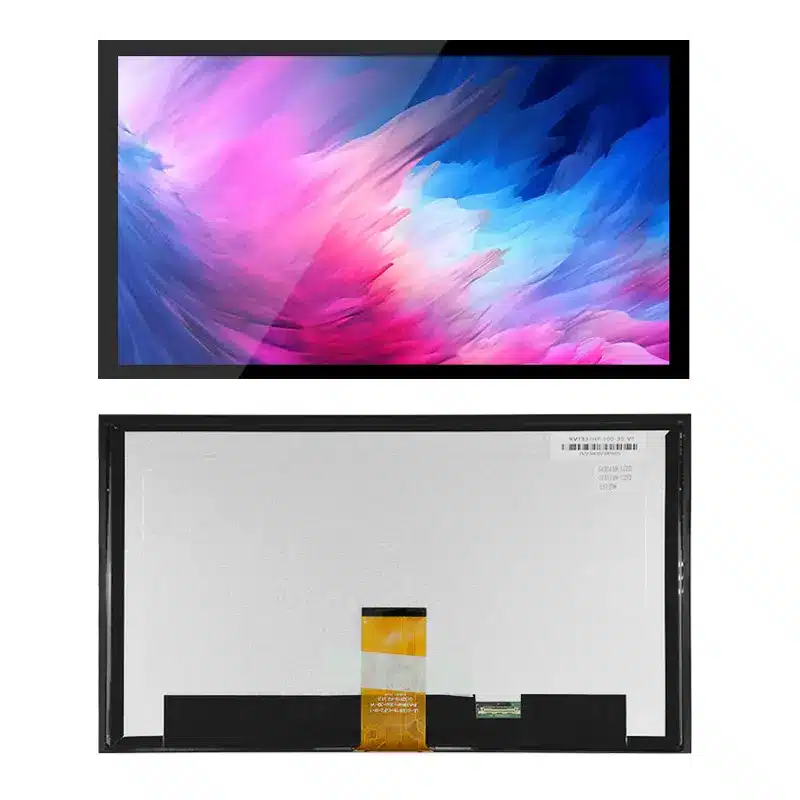
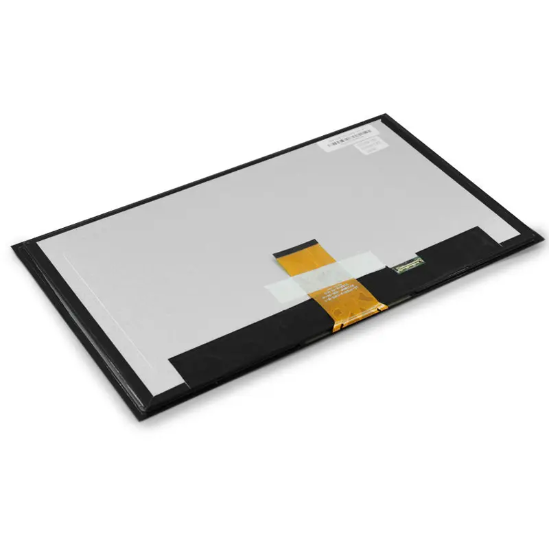
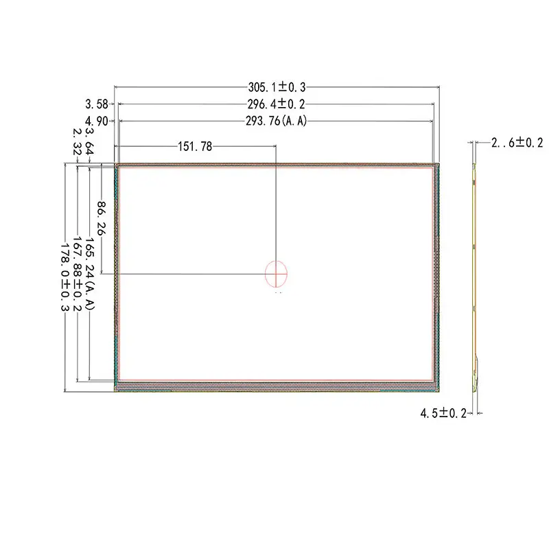
The 13.3 Inch Embedded eDP Display Module provides a 1920 × 1080 pixel workspace for equipment interfaces that need detailed graphics, structured menus, status information, and touch-based controls in a compact 16:9 format. Its active image area measures 293.76 × 165.24 mm, while the panel-profile reference is 305.1 × 178.0 × 2.6 mm.
The display path uses a 30-pin eDP connection. A G+G capacitive-touch assembly can be configured for the project, but its controller, communications interface, firmware, connector, cover lens, and bonding method must be defined separately.
Key Specifications at a Glance
| Specification | Value |
|---|---|
| Display size | 13.3 inch |
| Resolution | 1920 × 1080 pixels |
| Panel technology | IPS-type TFT LCD |
| Display interface | eDP |
| Display connection | 30 pin |
| Active area | 293.76 × 165.24 mm |
| Panel outline | 305.1 × 178.0 mm |
| Panel-profile reference | 2.6 mm |
| Local assembly profile | Approximately 4.5 ± 0.2 mm in the thicker region |
| Pixel pitch | 0.18 × 0.18 mm |
| Pixel arrangement | RGB vertical stripe |
| Display colors | 262K colors |
| Touch configuration | Project-defined G+G capacitive touch |
| Surface treatment | Anti-glare |
| Surface hardness | 3H |
| Operating temperature | −30°C to +70°C |
| Storage temperature | −40°C to +80°C |
Full HD Workspace for Embedded HMI Design
1920 × 1080 Interface Layout
Full HD resolution provides sufficient pixel capacity for interfaces that combine operating data, menus, diagrams, alerts, charts, camera windows, and graphical controls on one display. The familiar 16:9 layout also allows design teams to reuse established UI frameworks without adopting an unusual aspect ratio.
Resolution alone does not determine whether the interface will be comfortable to operate. Font size, UI scaling, touch-target dimensions, viewing distance, and the physical cover-lens opening should be checked on a sample before the interface is released.
Active Image Area and Pixel Pitch
The 293.76 × 165.24 mm active area defines the visible image region. It should not be confused with the complete 305.1 × 178.0 mm panel outline when calculating the bezel opening or adhesive overlap.
The 0.18 × 0.18 mm pixel pitch supports the 1920 × 1080 matrix across the 13.3-inch diagonal. Enclosure and cover-lens drawings should preserve the complete active area and avoid masking interface content near the edges.
30-Pin eDP Host Integration
Interface Compatibility Review
The display uses a 30-pin eDP connection, but pin count and connector appearance are only two parts of compatibility. The host platform and panel must also agree on:
- eDP link configuration
- Lane arrangement
- Resolution and timing
- Electrical levels
- Panel power requirements
- Backlight power and control
- Connector series
- Contact orientation
- Complete pin assignment
- Power-enable and backlight-control signals
A matching 30-pin connector does not by itself establish eDP timing, lane, voltage, or pin compatibility.
An HDMI, LVDS, MIPI DSI, USB, or conventional DisplayPort output cannot be connected directly unless the system includes the correct conversion and panel-power hardware.
Display and Touch Are Separate Signal Paths
The eDP connection carries display information. It does not automatically define or transport the capacitive-touch control path.
The eDP video connection does not define the capacitive-touch controller or its host interface.
The touch-equipped assembly may require a separate USB, I²C, or other project-defined connection, but no specific interface should be assumed until the touch-controller specification is approved.
Configuring the G+G Capacitive Touch Assembly
Touch Controller and Host Interface
The G+G capacitive-touch construction supports a rigid glass-based sensor arrangement for a custom HMI front surface. The supplied assembly should be specified as a complete system rather than as an unspecified touch layer.
The project definition should identify:
- Required touch interface
- Host operating system or firmware
- Touch-point requirement
- Touch controller
- Connector and FPC direction
- Supply voltage
- Cover-lens thickness
- Decorative printing
- Active touch area
- Edge and ground design
- Bonding method
- Environmental conditions
No touch-controller compatibility, gesture support, glove operation, water performance, stylus function, or touch lifetime should be assumed without confirmation.
Cover Lens and Bonding Inputs
The final cover-lens outline can affect the product’s complete dimensions, optical transmission, reflectance, touch tuning, and mounting arrangement. Anti-glare treatment and 3H surface hardness provide useful baseline characteristics, but they do not establish impact resistance, chemical resistance, waterproofing, or vandal resistance.
Projects requiring optical bonding should define the lens material, thickness, printing area, visible window, adhesive system, acceptable bubbles, optical target, and complete assembly depth.
Optical Qualification for the 13.3 Inch Embedded eDP Display Module
Luminance Value Confirmation
Luminance must be confirmed for the ordered configuration because both of the following value sets are associated with this design:
- 300 cd/m² typical
- 220 cd/m² typical and 200 cd/m² minimum
The approved optical specification should control production acceptance. A project requiring a particular finished-front brightness should also account for transmission losses through the touch sensor, cover lens, anti-glare surface, bonding layer, and decorative printing.
Brightness customization may require a project quantity of 5,000 pieces. The requested luminance, thermal constraints, backlight power, dimming method, expected lifetime, sample requirements, and annual demand should be submitted together.
Display-Mode Confirmation
The configuration has been described both as Normally Black and as Normally White. These modes are not interchangeable, so the final production specification must identify the applicable display mode.
A sample evaluation should verify:
- Dark-state appearance
- Contrast behavior
- Viewing consistency
- Color presentation
- Backlight uniformity
- Interface timing
- Required operating orientation
Numeric viewing angles and contrast ratio should be confirmed before they are used in a released system specification.
Slim Mechanical Integration
Panel Profile Versus Installed Stack
The LCD panel reference measures 305.1 × 178.0 × 2.6 mm. A local side-profile dimension of approximately 4.5 ± 0.2 mm is also associated with a thicker assembly region.
The 2.6 mm figure must not be treated as the complete installed depth when the design also includes:
- Capacitive-touch sensor
- Cover lens
- Optical or perimeter bonding
- Display FPC
- Touch FPC
- Connector clearance
- Cable bend radius
- Rear reinforcement
- Mounting adhesive
- Retention brackets
- Front bezel
Enclosure release should use the approved panel-and-touch assembly drawing because the 2.6 mm panel profile does not represent every installed stack component.
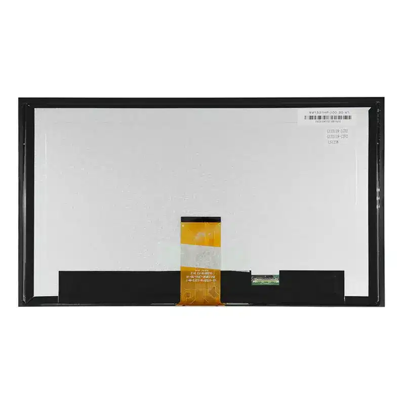
The rear connection region and FPC direction should be checked against the controller-board position before enclosure tooling begins.
Environmental and Surface Characteristics
The stated operating range is −30°C to +70°C, and the storage range is −40°C to +80°C. These temperature ranges support evaluation for equipment that experiences wider conditions than ordinary office electronics.
They do not, by themselves, establish:
- Industrial certification
- Automotive qualification
- Medical compliance
- EMC performance
- ESD level
- Vibration resistance
- Thermal-cycling life
- Humidity resistance
- Waterproofing
- Outdoor readability
- Continuous-service lifetime
Final qualification must cover the complete display, touch panel, cover lens, controller, backlight system, cables, enclosure, bonding process, and thermal design.
Application and Configuration Review
The 13.3 Inch Embedded eDP Display Module can be evaluated for:
- Embedded HMI consoles
- Equipment-control interfaces
- Machine setup displays
- Compact operator terminals
- Test and service equipment
- Production-information terminals
- Smart equipment panels
- Configuration consoles
- Monitoring interfaces
- Custom electronic systems
The module is an integration component rather than a finished monitor. Systems requiring HDMI input, USB touch, a controller board, enclosure, power supply, mounting frame, or a specific software environment need additional hardware and project definition.
Customization Scope
Project review may cover:
- G+G capacitive-touch assembly
- Touch controller and interface
- Cover-lens shape and printing
- Anti-glare or other surface requirements
- Optical or perimeter bonding
- FPC direction
- Connector configuration
- Cable design
- Luminance target
- Mechanical outline
- Documentation and labeling
Brightness customization may require a 5,000-piece quantity. Touch, cover-lens, bonding, cable, and mechanical changes are reviewed according to tooling, material availability, technical feasibility, and forecast demand. Sample and standard-module quantities are confirmed separately.
Procurement Checklist
Submit the following before sample approval:
- Host platform and processor
- Complete eDP output specification
- Required resolution and timing
- Lane configuration
- Logic and panel voltages
- Full 30-pin assignment
- Connector part number and orientation
- Backlight power and dimming requirements
- Touch-interface target
- Touch-point requirement
- Host operating system or firmware
- Cover-lens drawing
- Touch active area
- Bonding preference
- Enclosure and bezel-opening drawing
- FPC direction and bend restrictions
- Required approved luminance
- Required display mode
- Operating and storage conditions
- Compliance or reliability requirements
- Sample quantity
- Forecast annual demand
FAQ
About 13.3 Inch Embedded eDP Display Module
What must be checked before connecting this display to a 30-pin eDP host?
How should the G+G touch version be specified?
Which luminance value should be used for system design?
What depth should be reserved in the enclosure?
How should the display mode be qualified?
Freya Yang
+86 18318948097