Freya Yang
+86 18318948097
+852 62667476
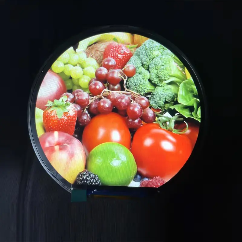
3.6 Inch eBike Gauge Display Assembly for Round Dashboards
Model P/N
Size
Resolution
Brightness
Viewing Angle
Connector Type
Operating Temp
Overall(mm)
huisoar
HS036H120A
Brand
Panel Size (inch)
Model P/N
Resolution
Brightness (nits)
Viewing Angle
Response Time
Overall (mm)
Active Area (mm)
Refresh Rate
Display Colors
Panel Type
Connector Type
Operating Temp
Touchscreen Type
Storage Temp
Work Mode
Pixel Format
Control Type
Operating Environment
Motherboard Type
Designed For
3.6 Inch eBike Gauge Display Assembly for Round Dashboards
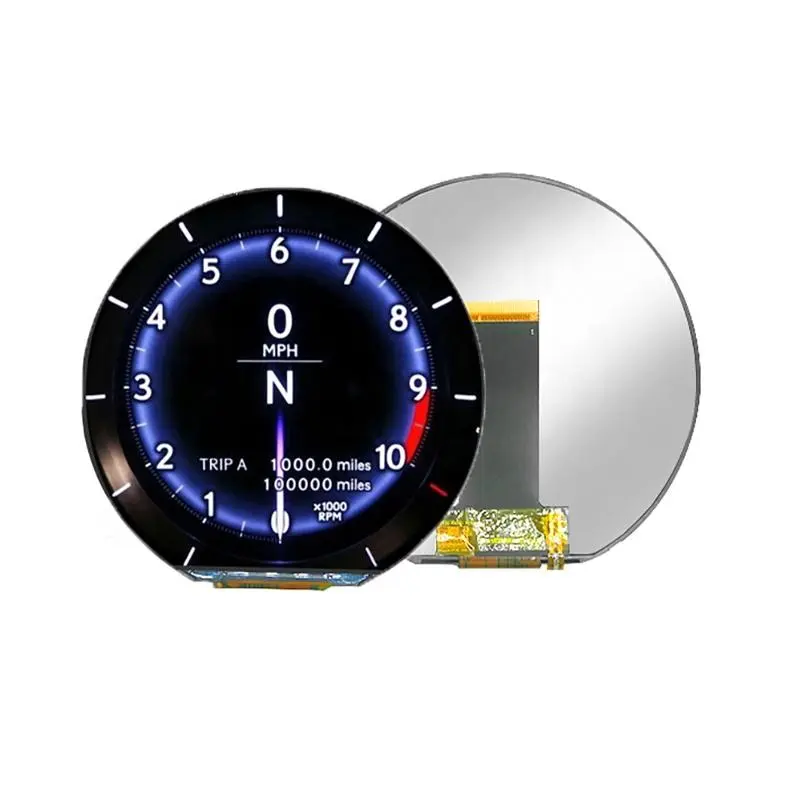
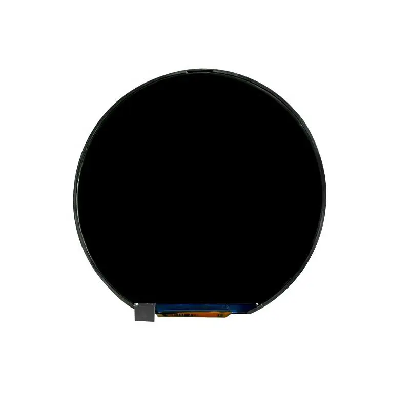
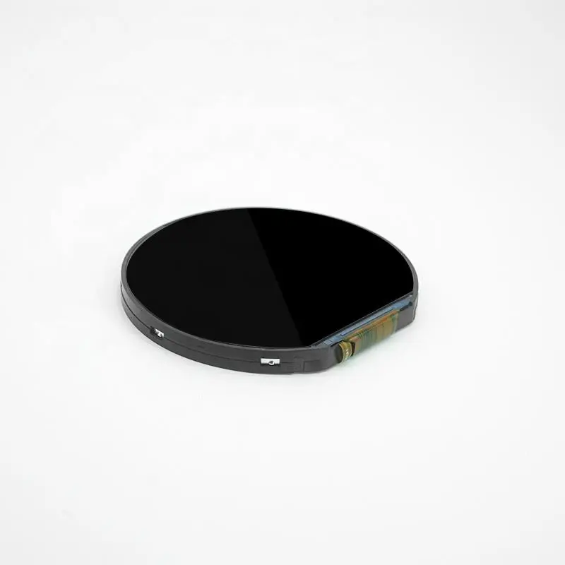
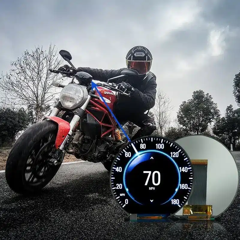
The eBike Gauge Display Assembly combines a 3.6-inch round IPS panel with a 544 × 506 pixel raster for electric-bike gauges, scooter dashboards and compact mobility instruments. Its normally black display mode, 16.7M-color output, white LED backlight and DPI interface support gauge-style interfaces that present speed, battery state, riding mode, warnings and system information within a circular visual area.
The module is a display component rather than a complete eBike dashboard. The host board, vehicle communication, power conversion, enclosure, controls, front protection and environmental sealing must be engineered separately.
Product Summary
This round IPS TFT module is intended for interfaces where a conventional rectangular panel would not match the dashboard styling or available mounting area.
The 544 × 506 raster supports detailed dial graphics, status icons, numerical values and segmented information zones. Because the horizontal and vertical pixel counts differ, the interface must be designed for the actual visible geometry rather than treated as a perfectly square digital canvas.
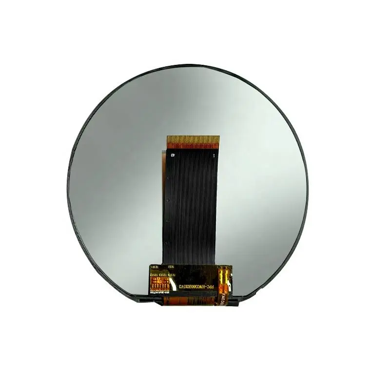
The module uses a DPI interface and a 40-pin FPC with a 0.5 mm pitch. Host compatibility depends on timing, pixel format, voltage levels, control signals and the complete pin assignment.
The standard configuration is treated as non-touch because no integrated touchscreen is confirmed.
Product Main Parameters
| Main parameter | Confirmed specification |
|---|---|
| Display size | 3.6 inches |
| Display geometry | Round |
| Resolution | 544 RGB × 506 pixels |
| Panel technology | IPS TFT LCD |
| Display mode | Normally black |
| Pixel arrangement | RGB vertical stripe |
| Display colors | 16.7M colors |
| Interface | DPI/RGB pixel interface |
| Connector | 40-pin FPC, 0.5 mm pitch |
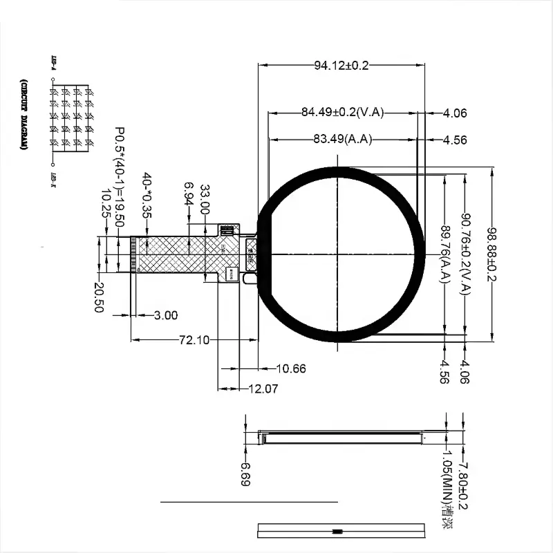
| Active area | 89.76 × 83.49 mm, drawing reference |
| Module outline | 98.88 × 94.12 × 7.80 mm, drawing reference |
| Pixel pitch | 55 × 165 μm |
| Control IC | ST72566 |
| Backlight | White LED |
| Operating temperature | −30°C to +85°C |
| Storage temperature | −30°C to +85°C |
| Touch status | No standard touch confirmed |
Building a 544 × 506 Circular Gauge Interface
Mapping the Non-Square Pixel Raster
The host graphics system should generate the native 544 × 506 frame without stretching it into a square resolution.
A circular safe-area mask should be applied during UI design. Important content should remain clear of the curved edges, including:
- speed values;
- battery percentage;
- warning symbols;
- riding-mode labels;
- navigation prompts;
- temperature or power indicators;
- connection status;
- service alerts.
Graphics should be tested on the physical module because a layout that appears balanced on a rectangular development monitor may look offset when viewed through a circular opening.
Prioritizing Riding Information
An eBike interface must remain easy to scan while the vehicle is moving.
The visual hierarchy should prioritize:
- current speed;
- battery or range status;
- riding mode;
- warnings;
- secondary trip information.
Large numerical values and high-contrast icons are generally more useful than dense menus. The interface should also account for the final cover lens, viewing distance and mounting angle.
DPI Integration for the eBike Gauge Display Assembly
Confirming the DPI/RGB Data Format
DPI normally represents a direct pixel-data connection, but the interface name alone is not a complete electrical specification.
The host review must confirm:
- pixel-clock frequency;
- horizontal and vertical timing;
- RGB data width;
- synchronization polarity;
- data-enable behavior;
- voltage levels;
- reset or enable signals;
- image orientation;
- frame rate;
- panel and backlight power.
A processor with an RGB or DPI output may still require timing, voltage or pin-mapping changes before it can drive the panel.
Qualifying the 40-Pin FPC
A 40-pin connector does not guarantee compatibility with another 40-pin display.
Confirm:
- complete pin assignment;
- FPC contact side;
- pin-1 location;
- insertion direction;
- 0.5 mm connector pitch;
- data-line allocation;
- clock and synchronization signals;
- power and ground pins;
- backlight connections;
- reserved pins;
- FPC bend radius.
The drawing also indicates a substantial FPC extension that must be included in the dashboard packaging study.
ST72566 Documentation Boundary
ST72566 is identified as the panel control IC.
The identifier alone does not establish:
- host initialization commands;
- register programming;
- power sequencing;
- supported controller boards;
- RGB bit depth;
- exact timing;
- voltage requirements.
The complete panel specification and approved pin table must control the host design.
IPS Image Performance and Backlight Planning
The IPS structure supports stable image presentation across the normal viewing positions expected around a handlebar or dashboard installation.
The module uses a white LED backlight, but the exact luminance, LED electrical requirement, dimming method and backlight lifetime are not confirmed for this configuration.
Final readability should therefore be tested with:
- the intended cover lens;
- actual riding-light conditions;
- dashboard recess depth;
- UI colors;
- operator viewing angle;
- backlight-driver settings;
- enclosure temperature.
No sunlight-readable value should be assigned until the approved optical specification confirms the luminance and completed assembly performance.
Mechanical Integration for Round Dashboards
The detailed drawing provisionally indicates:
- 89.76 × 83.49 mm active area;
- 98.88 × 94.12 mm module envelope;
- 7.80 mm maximum thickness reference;
- 40-pin, 0.5 mm-pitch FPC;
- extended lower FPC structure.
The commercial tables contain different active-area and outline values. The approved production drawing must therefore be confirmed before tooling.
Dashboard design should account for:
- round bezel opening;
- active-area centering;
- FPC exit and bend;
- connector access;
- rear-component clearance;
- pressure-free glass zones;
- cover-lens spacing;
- adhesive or bracket position;
- service access;
- tolerance stack.
Temperature Range and Vehicle Qualification
The component is specified for operation and storage from −30°C to +85°C.
That temperature range is useful for mobility-equipment evaluation, but it does not independently establish:
- automotive qualification;
- vibration resistance;
- shock resistance;
- water resistance;
- condensation resistance;
- ultraviolet resistance;
- electromagnetic compatibility;
- continuous outdoor lifetime.
The finished dashboard assembly requires its own mechanical, electrical and environmental validation.
Recommended Application Routes
The display may be evaluated for:
- eBike speed and battery gauges;
- electric-scooter dashboards;
- motorcycle-style auxiliary instruments;
- compact mobility-control panels;
- protected vehicle status displays;
- smart-home rotary controls;
- industrial round gauges.
In late-stage selection, the eBike Gauge Display Assembly should be evaluated by native timing, FPC definition, optical performance, enclosure fit and environmental requirements rather than by shape alone.
These are integration routes, not certification or compatibility claims.
Customization and Sample Qualification
Project review may cover:
- cover-lens shape;
- printed border;
- touch-panel integration;
- optical treatment;
- FPC layout;
- connector definition;
- brightness target;
- backlight driver;
- controller-board matching;
- mechanical adaptation;
- packaging.
Custom configurations are generally reviewed from 500 pieces, subject to tooling requirements, material availability and the requested specification. Sample and standard-module quantities are confirmed separately.
A representative sample should be tested for:
- native 544 × 506 image output;
- DPI timing stability;
- correct color order;
- image orientation;
- FPC alignment;
- circular UI centering;
- cold startup;
- high-temperature operation;
- backlight behavior;
- enclosure fit.
Procurement Checklist
Submit the following before sample or production approval:
- native 544 × 506 timing;
- DPI/RGB data format;
- required color depth;
- complete 40-pin assignment;
- FPC contact side and pin 1;
- panel-voltage requirements;
- backlight voltage and current;
- synchronization polarity;
- active-area and outline drawing;
- circular UI safe area;
- cover-lens requirement;
- touch or non-touch selection;
- target lighting;
- mounting orientation;
- operating environment;
- sample quantity;
- annual demand;
- qualification plan;
- production schedule.
FAQ
About 3.6 inch eBike Gauge Display Assembly
What must be checked before connecting the module to a DPI host?
How should graphics be prepared for the round viewing area?
Which mechanical dimensions should control the enclosure?
Does the −30°C to +85°C range establish automotive qualification?
Is a touchscreen included in the standard module?
Freya Yang
+86 18318948097