Freya Yang
+86 18318948097
+852 62667476
7 Inch TTL RGB TFT Screen LCD Modules for Industrial HMI
Model P/N
Size
Resolution
Brightness
Viewing Angle
Connector Type
Operating Temp
Overall(mm)
huisoar
HS070AT9309A-V2
Brand
Panel Size (inch)
Model P/N
Resolution
Brightness (nits)
Viewing Angle
Response Time
Overall (mm)
Active Area (mm)
Refresh Rate
Display Colors
Panel Type
Connector Type
Operating Temp
Touchscreen Type
Storage Temp
Work Mode
Pixel Format
Control Type
Operating Environment
Designed For
7 Inch TTL RGB TFT Screen LCD Modules for Industrial HMI
A 7-inch landscape TFT module with native 800×480 TTL RGB input for embedded control interfaces.
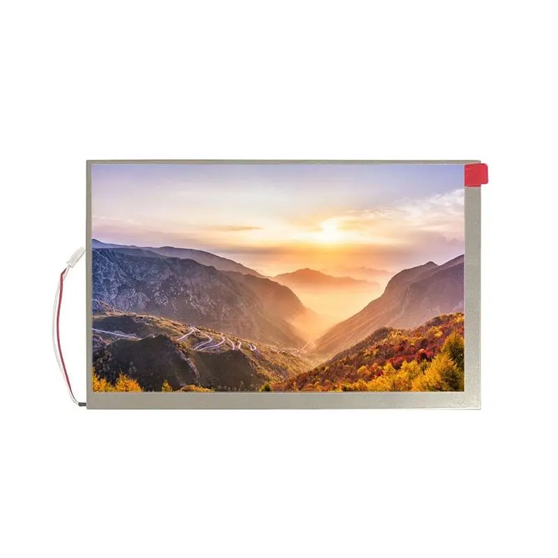
The 7 Inch TTL RGB TFT Screen LCD Modules route is designed for embedded equipment that can generate native parallel RGB video. The 7.0-inch panel combines an 800×480 landscape format, a normally black a-Si TFT structure, a 152.40 × 91.44 mm active area, and a 40-pin FPC connection for control panels, equipment dashboards, compact operator stations, and legacy embedded platforms.
This is a bare LCD module rather than a complete monitor, touchscreen, or video-controller assembly.
Key Specifications at a Glance
| Parameter | Value |
|---|---|
| Size | 7.0 inch |
| Resolution | 800 × 480 pixels |
| Panel technology | a-Si TFT active matrix |
| Display mode | Normally black |
| Interface | Digital TTL / parallel RGB |
| Connector | 40-pin FPC |
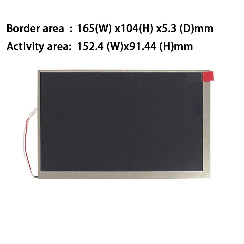
| Active area | 152.40 × 91.44 mm |
| Module outline | 165.00 × 104.09 × 5.30 mm |
| Center luminance | 350 cd/m² typical |
| Panel power | 0.66 W typical |
| Backlight power | 1.5 W typical |
The final design must be approved against the complete timing, voltage, pin-assignment, FPC, and backlight requirements.
800×480 Interface Design
The native 800×480 layout provides a practical balance between display area and host graphics demand. It is well suited to equipment interfaces that show status values, menus, alarms, trend graphics, operating instructions, and touch-style buttons even when no physical touch panel is installed.
Native-resolution graphics
The host should generate content at 800×480 pixels. Scaling a different framebuffer format may reduce text clarity and can add processing or controller complexity.
UI designers should test font weight, icon dimensions, line thickness, and data density on the physical 7-inch panel.
Normally black presentation
The normally black display mode produces a dark inactive appearance and can support equipment interfaces with dark backgrounds, illuminated controls, status colors, and high-contrast text.
No contrast-ratio value is confirmed, so the finished interface should be evaluated with the actual panel and cover structure.
Active image area
The active image region measures 152.40 × 91.44 mm. The enclosure window should follow the approved mechanical drawing rather than the active-area values alone.
TTL RGB Interface Compatibility
The Digital TTL connection is a native parallel RGB display interface. The host must provide the correct pixel data, pixel clock, synchronization, data-enable behavior, voltage levels, and control signals.
Host signals to confirm
Before PCB release, verify:
- RGB data mapping
- Pixel-clock frequency
- Horizontal synchronization
- Vertical synchronization
- Data-enable behavior
- Power and logic voltages
- Reset or display-enable requirements
- Backlight enable and regulation
- Complete 40-pin assignment
- FPC pitch and contact side
A matching resolution does not prove electrical compatibility.
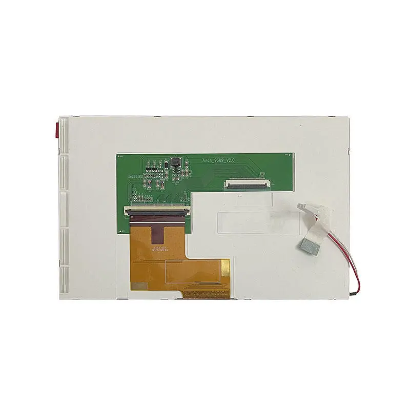
40-pin FPC compatibility
A 40-pin FPC does not establish compatibility with another 40-pin LCD module.
Pin order, signal count, voltage levels, backlight connections, unused pins, connector orientation, and cable contact side must all match.
Interfaces requiring conversion
HDMI, MIPI DSI, LVDS, eDP, DisplayPort, and USB video cannot drive the native TTL RGB path directly. An appropriate bridge or controller board is required.
Controller selection must use the full timing and pin-assignment documentation rather than the diagonal size and resolution alone.
Mechanical Integration of 7 Inch TTL RGB TFT Screen LCD Modules
The module outline is 165.00 × 104.09 × 5.30 mm. This provides a conventional landscape form factor for embedded bezels, machine controls, and equipment housings.
Enclosure and bezel planning
The enclosure design should account for:
- Active-area alignment
- Panel border and bezel overlap
- Module tolerances
- FPC exit location
- Backlight-wire routing
- Connector access
- Rear-component clearance
- Assembly and service access
The window should not be dimensioned solely from the nominal seven-inch diagonal.
FPC routing
The FPC should be routed without sharp folds, trapped sections, or pressure from mounting bosses. The connector area requires enough clearance for insertion, locking, and replacement.
Backlight-wire clearance
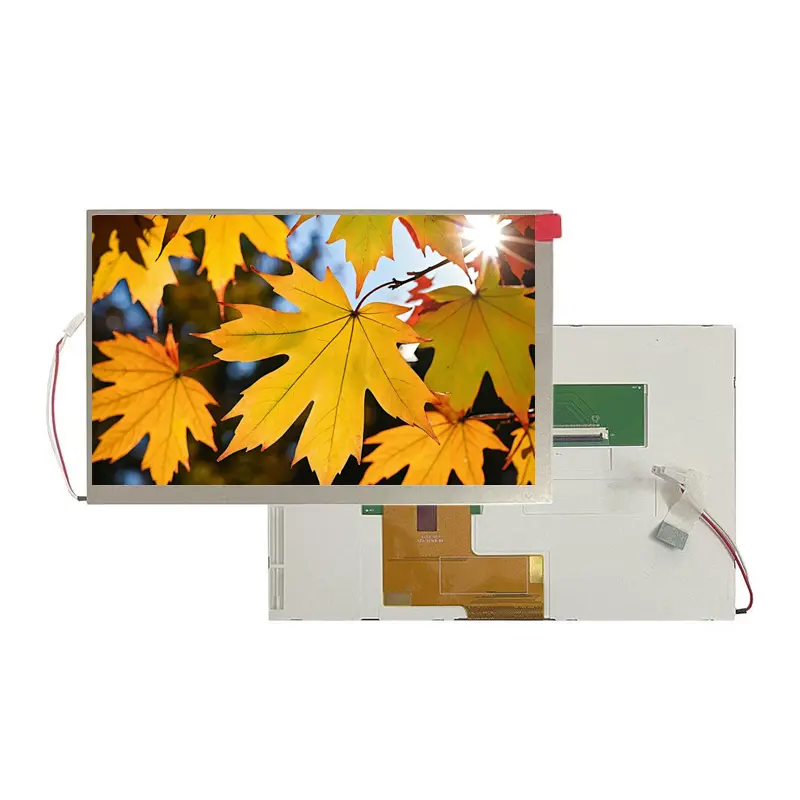
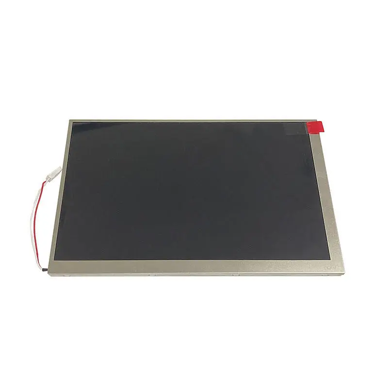
The panel photographs show a separate backlight-wire route. The final enclosure should avoid pinching the wires or placing them against sharp metal edges.
Luminance and Power Planning
The center luminance is 350 cd/m² typical. This standard optical level is intended primarily for indoor or controlled-light environments.
The value does not establish direct-sunlight readability.
Panel consumption
The TFT panel consumption is listed as 0.66 W typical. This value should be preserved as a typical operating reference rather than treated as a guaranteed maximum.
Backlight consumption
The backlight consumption is 1.5 W typical. The system design must include a suitable backlight driver and any required enable or brightness-control functions.
Thermal and power margin
The host supply and enclosure should be designed with margin for startup behavior, component tolerance, backlight regulation, and the operating conditions of the completed device.
Recommended Applications
The module is suitable for:
- Industrial HMI control panels
- Embedded equipment dashboards
- Building-control interfaces
- Compact POS operator interfaces
- Portable test and service equipment
- Machine configuration panels
- Legacy parallel-RGB platforms
- Equipment status and monitoring displays
Medical, automotive, outdoor, safety-critical, and payment-related applications require separate system and regulatory qualification.
Touch and Customization Scope
No touch panel is confirmed for the standard module. A touchscreen requirement should be treated as a separate assembly specification.
Project review can cover:
- LCD size and resolution
- Interface and pin definition
- FPC shape and material
- Brightness target
- Mechanical adaptation
- Touch-panel integration
- Cover structure
- Controller-board matching
Custom configurations are generally reviewed from 500 pieces, subject to tooling requirements, material availability, and the requested specification. Sample and standard-module quantities are confirmed separately.
Procurement and Sample Approval Checklist
Confirm:
- Native 800×480 timing
- RGB data mapping
- Pixel clock and synchronization
- Data-enable behavior
- Complete 40-pin assignment
- FPC pitch and contact orientation
- Panel and logic voltage levels
- Backlight-driver compatibility
- 350 cd/m² typical luminance requirement
- 152.40 × 91.44 mm active area
- 165.00 × 104.09 × 5.30 mm module fit
- Touch requirement
- Cover and enclosure design
- Operating environment
- Sample quantity
- Estimated annual demand
- Production timing
- Controller-board requirement
FAQ
About 7 Inch TTL RGB TFT Screen LCD Modules
How should the 0.66 W panel power and 1.5 W backlight power be used in a system power budget?
Does the 152.40 × 91.44 mm active area determine the required bezel opening?
What UI density is practical on a 7-inch 800×480 landscape panel?
When is an 800×480 TTL RGB module a better choice than a higher-resolution panel?
What symptoms can indicate incorrect RGB data mapping or timing?
Can the module outline be used to determine whether it will replace an existing seven-inch LCD?
How should typical luminance be interpreted during incoming inspection?
What should be reviewed when adding a custom FPC to this module?
How can backlight-wire routing affect long-term reliability?
Freya Yang
+86 18318948097