Freya Yang
+86 18318948097
+852 62667476
6.9 Inch Vertical Control Touchscreen Module for Appliances
Model P/N
Size
Resolution
Brightness
Viewing Angle
Connector Type
Operating Temp
Overall(mm)
huisoar
HS700066S0-CTP
Brand
Panel Size (inch)
Model P/N
Resolution
Brightness (nits)
Viewing Angle
Contrast Ratio
Response Time
Overall (mm)
Active Area (mm)
Refresh Rate
Display Colors
Panel Type
Connector Type
Operating Temp
Touchscreen Type
Storage Temp
Work Mode
Pixel Format
Control Type
Operating Environment
Designed For
6.9 Inch Vertical Control Touchscreen Module for Appliances
This narrow IPS touch assembly provides a native 280 × 1424 interface and MIPI display input for modern appliance-control layouts.
Product Summary
The Vertical Control Touchscreen Module is designed for equipment that needs a tall, interactive user interface in a limited-width front panel. Its 280 × 1424 resolution supports vertically arranged temperature settings, timers, operating modes, progress graphics, alerts, menus and equipment-status information.
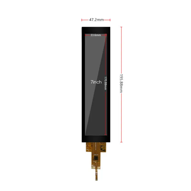
The combined module uses projected capacitive touch, IPS viewing and 600 cd/m² typical panel luminance. Its 47.20 × 195.88 × 5.50 mm outline is suitable for appliance fascia panels, narrow equipment controls and other embedded HMI structures where a conventional landscape display would consume excessive horizontal space.
Key Specifications
| Specification | Value |
|---|---|
| Display size | 6.9 inch |
| Resolution | 280 × 1424 pixels |
| Active area | 33.60 × 170.88 mm |
| Combined module outline | 47.20 × 195.88 × 5.50 mm |
| Panel technology | a-Si IPS TFT-LCD |
| Optical mode | Transmissive |
| Pixel arrangement | RGB stripe |
| Luminance | 600 cd/m² typical |
| Contrast ratio | 1000:1 typical |
| Viewing angle | 80°/80°/80°/80°, L/R/U/D |
| Display colors | 16.7M colors |
| Display interface | MIPI |
| Connection | 30-pin FPC |
| Touch type | Projected capacitive touch |
| Backlight | WLED |
| Operating temperature | −20°C to +70°C |
| Storage temperature | −30°C to +80°C |
280 × 1424 Vertical Touch Interface Design
Native Vertical UI Layout
The native raster is optimized for a narrow top-to-bottom interface. Product designers can divide the screen into clearly separated zones for:
- Temperature and setpoint values
- Appliance operating modes
- Timers and countdowns
- Progress indicators
- Fan or power levels
- Alarm and service messages
- Menu navigation
- Lock and safety status
- Connectivity indicators
- Brand graphics
Driving the panel at its native 280 × 1424 resolution helps preserve typography, icon shape, line width and touch-target alignment. Adapting a conventional landscape interface without redesign may produce small labels, inefficient empty areas or distorted graphics.
Touch-Target Planning
The active display area is 33.60 × 170.88 mm, but the combined touch assembly is wider and taller. Touch buttons should be sized for the intended user, mounting height and operating environment rather than being placed only according to pixel density.
Critical functions should remain inside a validated interaction safe area. Printed borders, cover-glass masking, bezel overlap, adhesive tolerances and enclosure alignment can reduce the usable visual and touch region.
IPS Viewing and 600 cd/m² Luminance
Controlled-Light Visibility
The panel provides 600 cd/m² typical luminance. This makes it suitable for evaluation in bright indoor appliances, equipment rooms and other controlled-light environments.
A 600 cd/m² panel does not by itself establish finished-system daylight readability behind cover glass.
Finished-front visibility depends on:
- Cover-glass transmission
- Touch-sensor transmission
- Adhesive or air-gap structure
- Printed border design
- Surface reflections
- Viewing angle
- Ambient lighting
- Optical bonding
- Anti-glare or anti-reflective treatment
The complete assembly should be tested under the actual installation lighting.
Cover-Glass Optical Losses
A touch module adds optical and mechanical layers beyond the bare LCD. These layers can reduce luminance and increase reflections if the stack is not properly designed.
Engineering review should therefore evaluate the selected cover lens, decorative printing, sensor construction, bonding method and front-surface treatment as one optical system rather than qualifying the LCD brightness alone.
MIPI and Touch Integration Requirements
MIPI Host Qualification
The display uses a 30-pin MIPI connection.
A 30-pin MIPI connector does not guarantee lane, timing, voltage, initialization or pin compatibility with another panel.
Before PCB or cable release, confirm:
- MIPI DSI lane count
- Clock-lane position
- Data-lane mapping
- Command or video mode
- Native horizontal and vertical timing
- Pixel format
- Link frequency
- Low-power and high-speed requirements
- Panel supply rails
- Reset and enable signals
- Backlight control
- Full 30-pin assignment
- Connector pitch
- Contact side
- Pin-1 orientation
- Approved initialization command package
Matching only the resolution or pin count is not sufficient for replacement qualification.
Separate Touch-Control Path
The display path and projected-capacitive-touch path must be qualified separately unless the approved specification explicitly combines them.
The touch section may require its own:
- Controller
- Communication bus
- Supply voltage
- Reset line
- Interrupt line
- I²C address or alternative protocol
- Firmware package
- Touch-point configuration
- Coordinate orientation
- Noise and sensitivity tuning
Touch communication should not be assumed to travel over the MIPI display link. The approved combined-module documentation must define both paths.
Mechanical Fit of the Vertical Control Touchscreen Module
Combined Touch-Assembly Dimensions
The Vertical Control Touchscreen Module measures 47.20 × 195.88 × 5.50 mm. The active display region is 33.60 × 170.88 mm, leaving space around the screen for the touch structure, printed border and mechanical stack.
Mechanical design should confirm:
- Front opening
- Visible-area alignment
- Printed mask width
- Cover-glass dimensions
- Corner radius
- Adhesive stack
- Rear-component clearance
- Touch and display FPC exits
- Bend radius
- Connector position
- Mounting pressure
- Tolerance accumulation
- Thermal expansion
- Service access
Use an approved combined drawing before releasing the enclosure, cover-glass printing, adhesive die cutting or tooling.
FPC and Rear Clearance
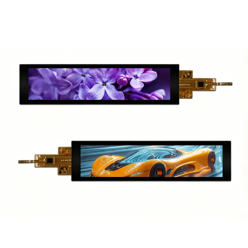
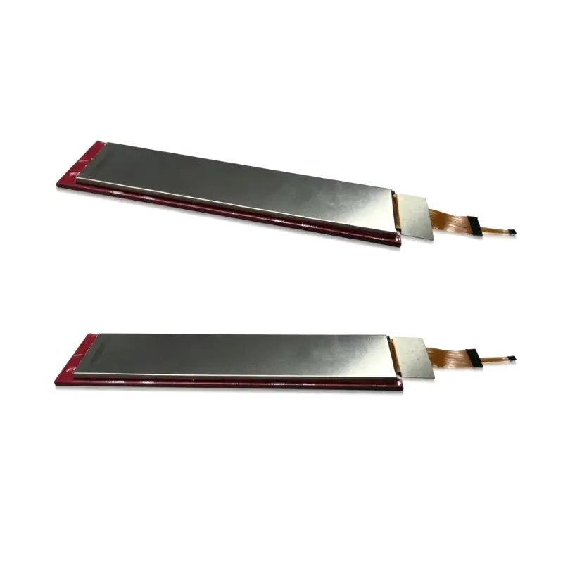
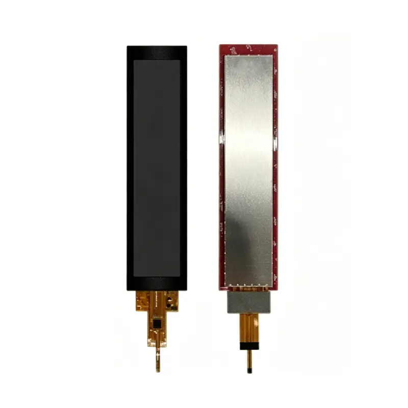
The product images show a long lower connection structure. The FPC tails must not be sharply bent, compressed or loaded at their bonded regions.
Prototype review should inspect:
- FPC direction
- Display-versus-touch connector separation
- Contact-side orientation
- Strain relief
- Connector retention
- Rear housing clearance
- Cable interference
- Adhesive compression
- Module flatness
- Assembly repeatability
Appliance and Equipment Applications
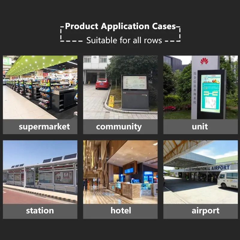
This module can be evaluated for:
- Refrigerator control panels
- Washing-machine display strips
- Air-conditioner interfaces
- Kitchen-appliance controls
- Vertical industrial HMIs
- Narrow machine command panels
- Equipment-status interfaces
- Selected healthcare-equipment control surfaces
For appliance projects, the product-level qualification plan should include electrical safety, EMC, moisture and contamination conditions, cleaning exposure, touch performance, temperature cycling and long-term front-panel reliability.
Medical-equipment suitability is not established by the display specifications alone. Any healthcare application requires completed-device risk management, electrical-safety review, software validation, usability engineering, environmental qualification and applicable regulatory documentation.
Customization and Qualification Boundaries
Project review can include:
- MIPI host and lane matching
- Complete 30-pin definition
- Initialization-package review
- Display and touch FPC adaptation
- Touch-controller selection
- Touch firmware and sensitivity tuning
- Cover-glass design
- Decorative printing
- Anti-glare or anti-reflective treatment
- Air or optical bonding
- Brightness target
- Enclosure adaptation
- Connector-board development
- Branding and packaging
- Sample validation
Custom configurations are generally reviewed from 500 pieces, subject to tooling requirements, material availability and the requested specification. Sample and standard-module quantities are confirmed separately.
Procurement Checklist
Submit:
- Host processor or controller model
- Native 280 × 1424 timing requirement
- MIPI DSI lane count and operating mode
- Required pixel format
- Complete 30-pin assignment
- Panel and logic power rails
- Reset and enable requirements
- Approved initialization package
- Backlight-driver requirements
- Dimming method
- Touch-controller model, when already selected
- Touch communication protocol
- Touch interrupt and reset routing
- Required touch-point count
- Display and touch FPC drawings
- Connector pitch and contact side
- Pin-1 orientation
- Combined mechanical drawing
- Front-window and cover-glass drawings
- Optical bonding requirement
- Target finished-front luminance
- Operating environment
- Sample quantity
- Annual demand
- Production schedule
FAQ
About 6.9 Inch Vertical Control Touchscreen Module
What must be checked before connecting a 30-pin MIPI host?
Is touch communication carried through the MIPI display interface?
How should a 280 × 1424 touch interface be designed?
Is 600 cd/m² sufficient behind a touch cover?
Which dimensions control enclosure release?
Freya Yang
+86 18318948097