Freya Yang
+86 18318948097
+852 62667476
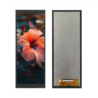
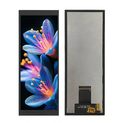
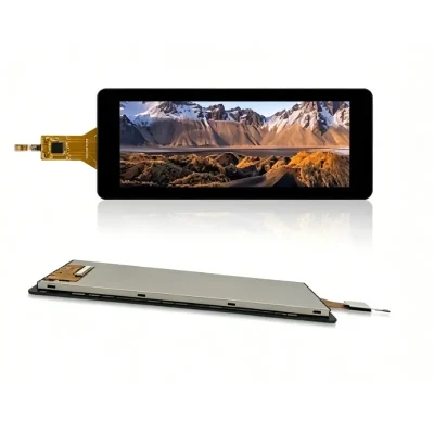
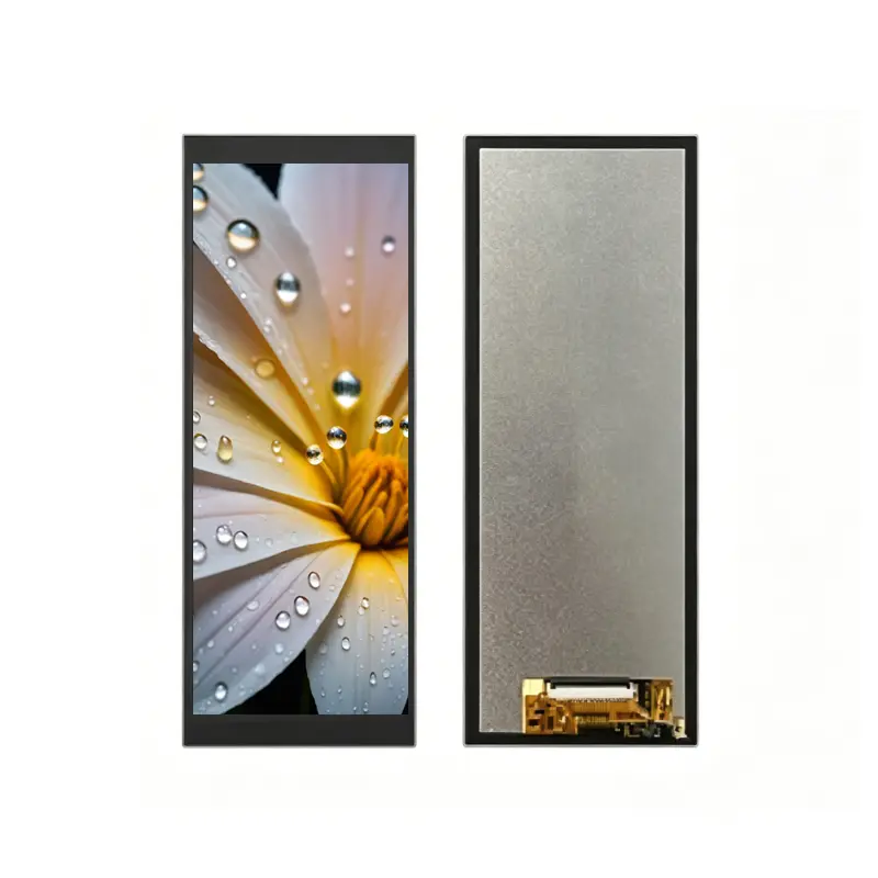
6.86 Inch Smart Appliance Status Menu Display Module
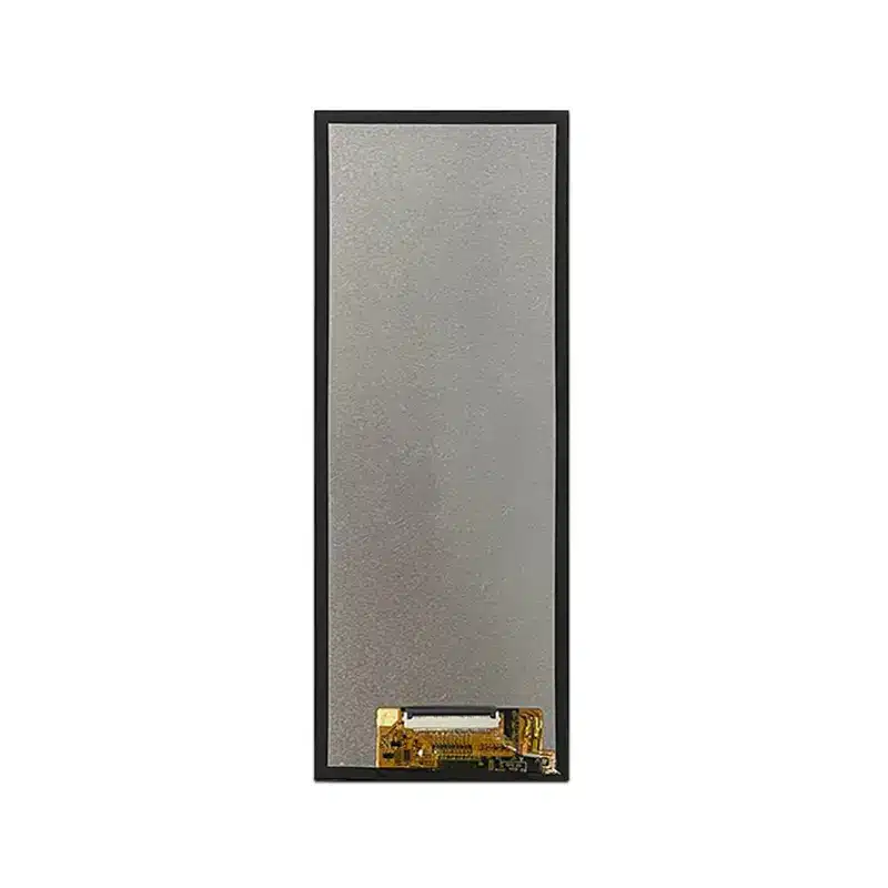
Model P/N
Size
Resolution
Brightness
Viewing Angle
Connector Type
Operating Temp
Overall(mm)
huisoar
HS686017B0
Brand
Panel Size (inch)
Model P/N
Resolution
Brightness (nits)
Viewing Angle
Contrast Ratio
Response Time
Overall (mm)
Active Area (mm)
Refresh Rate
Display Colors
Panel Type
Connector Type
Operating Temp
Touchscreen Type
Storage Temp
Work Mode
Control Type
Operating Environment
Motherboard Type
Designed For
6.86 Inch Smart Appliance Status Menu Display Module
The Smart Appliance Status Menu Display Module combines a native 480 × 1280 IPS panel, 500 cd/m² luminance and 40-pin LVDS integration for vertical control interfaces.
Product Summary
The Smart Appliance Status Menu Display Module provides a tall, narrow screen for operating modes, temperature settings, cycle progress, warnings and function menus in modern appliance panels. Its portrait geometry allows equipment designers to place a detailed graphical interface in a limited-width installation zone without using a conventional landscape display.
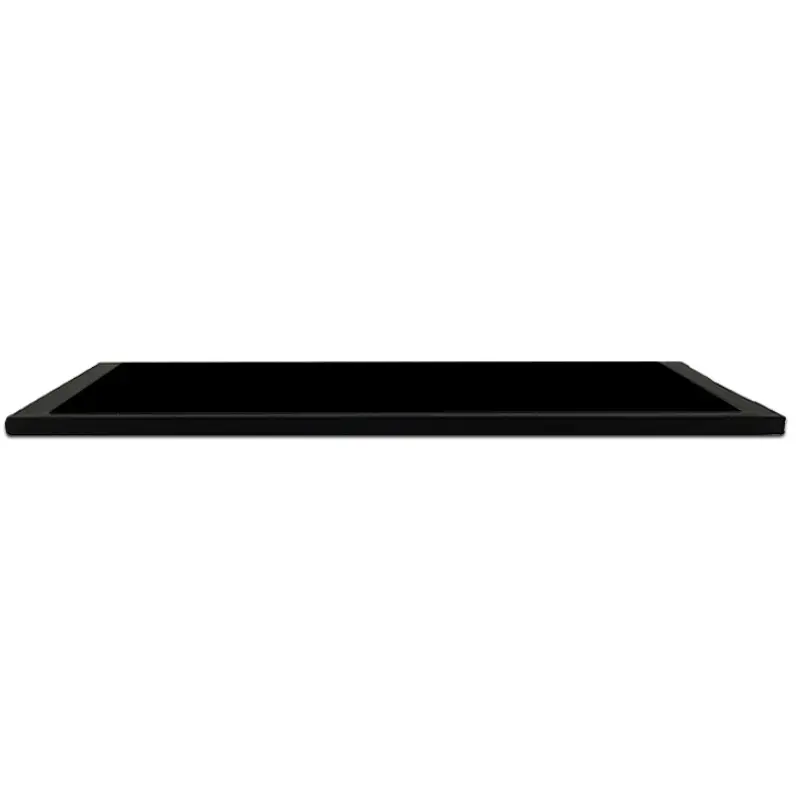
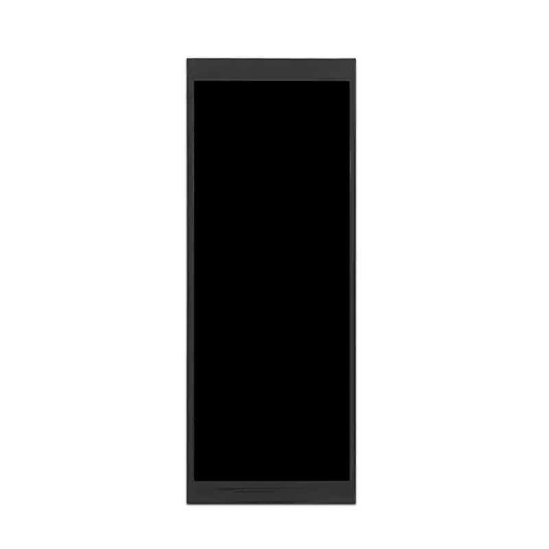
The 6.86-inch panel offers a 60.19 × 160.51 mm active area inside a 66.7 × 181.2 × 4.4 mm module outline. It combines IPS viewing, 500 cd/m² typical luminance, a 1500:1 typical contrast ratio and a 40-pin LVDS connection. The standard configuration is non-touch.
Key Specifications
| Parameter | Value |
|---|---|
| Display size | 6.86 inch |
| Resolution | 480 × 1280 pixels |
| Format | Portrait bar, approximately 3:8 |
| Panel type | IPS a-Si TFT-LCD |
| Optical structure | Transmissive |
| Luminance | 500 cd/m² typical |
| Contrast ratio | 1500:1 typical |
| Viewing angle | 80/80/80/80, L/R/U/D |
| Display colors | 16.7M |
| Interface | 40-pin LVDS |
| Active area | 60.19 × 160.51 mm |
| Overall size | 66.7 × 181.2 × 4.4 mm |
| Backlight | WLED |
| Touch | Non-touch |
| Operating temperature | −20°C to +70°C |
| Storage temperature | −30°C to +80°C |
Native 480 × 1280 Vertical Interface Design
Appliance Status and Menu Zones
The portrait raster supports information that follows a top-to-bottom sequence. A typical appliance interface can allocate separate zones for:
- operating mode
- cycle progress
- temperature
- timing
- fan or power level
- energy status
- warning messages
- maintenance prompts
- connectivity status
- function menus
This structure is suitable for refrigerators, ovens, range hoods, washing machines, energy-storage equipment and other products with narrow front-panel areas.
Native-Raster Software Preparation
The interface should be created directly for the native 480 × 1280 raster.
Before software approval, validate:
- portrait orientation
- native panel timing
- font scaling
- icon size
- list spacing
- warning-message position
- content-safe margins
- language expansion
- boot-screen dimensions
- animation behavior
Rotating a finished landscape interface without redesign may create unused areas, inconsistent spacing or difficult-to-read menu elements.
IPS Optical Performance for Appliance Panels
500 cd/m² Luminance Boundary
The panel is specified at 500 cd/m² typical luminance. This supports indoor appliances, utility equipment and controlled environments with moderate ambient lighting.
A 500 cd/m² panel is intended primarily for indoor or controlled-light equipment after front-glass losses are considered.
Finished visibility also depends on:
- front-lens transmission
- surface reflections
- air-gap construction
- optical bonding
- installation angle
- room lighting
- operator viewing position
The luminance specification does not establish direct-sunlight or outdoor readability.
Viewing Angle, Contrast and Color
The panel provides 80/80/80/80 viewing angles in the left, right, upper and lower directions. This supports appliances viewed while standing, walking past the product or operating it from an off-center position.
The 1500:1 typical contrast ratio supports strong separation between background areas, white text, icons and warning graphics. The 16.7M-color capability supports graphical menus and branded interfaces, but it does not establish calibrated color accuracy or a defined color gamut.
40-Pin LVDS Host Integration
Timing, Mapping and Pinout Qualification
A 40-pin LVDS connector does not guarantee timing, voltage, channel, bit-depth or pin compatibility with another panel.
Before designing a cable or applying power, confirm:
- native 480 × 1280 timing
- LVDS channel count
- LVDS bit configuration
- signal mapping
- signal voltage
- complete 40-pin assignment
- connector pitch
- contact side
- connector orientation
- panel supply
- backlight voltage and current
- backlight enable and dimming
- cable length and routing
Another 6.86-inch 480 × 1280 panel may use MIPI, RGB or a different LVDS definition, so size and resolution alone do not establish interchangeability.
NV3051F1 Documentation Boundaries
The NV3051F1 identifier helps distinguish this display configuration, but it does not independently establish the host initialization or power requirements.
Engineering approval should use:
- the complete panel specification
- native timing
- full pin definition
- electrical limits
- reset requirements
- power sequence
- backlight-control definition
- approved controller documentation
Register or initialization data from an unrelated NV3051F1 display should not be copied without model-specific verification.
Smart Appliance Status Menu Display Module Mechanics
Active Area and Visible Opening
The active image area is 60.19 × 160.51 mm. This value should guide:
- visible bezel opening
- front-lens window
- printed black mask
- panel alignment
- UI-safe margins
- menu-column width
- warning-icon placement
Critical operating values and warning messages should remain inside the approved visible opening after bezel overlap and manufacturing tolerances are applied.
Outline and Cable Clearance
The complete module measures 66.7 × 181.2 × 4.4 mm.
Mechanical review should confirm:
- complete panel outline
- active-area position
- connector location
- cable exit
- cable bend radius
- rear clearance
- mounting support
- front-lens overlap
- enclosure tolerances
- service access
The precise dimensions should control tooling rather than rounded 66 × 181 × 4 mm references.
Temperature Qualification
The module is specified for operation from −20°C to +70°C and storage from −30°C to +80°C.
These limits support evaluation in appliances, utility equipment and selected embedded-control environments, but they do not independently establish certification for a particular product category.
System-level qualification should consider:
- cold startup
- high-temperature image behavior
- backlight output across temperature
- controller temperature
- enclosure heat
- condensation
- cable flexibility
- repeated thermal cycling
- cleaning and service conditions
Testing should use the final controller, front lens and enclosure.
Non-Touch Appliance Architecture
The standard module is non-touch. It is suitable where user input is provided through:
- physical buttons
- rotary controls
- membrane keys
- capacitive keys outside the display
- a separate keypad
- remote software
- an independently developed touch assembly
Potential applications include:
- refrigerator status panels
- oven controls
- range-hood interfaces
- washing-machine menus
- energy-storage equipment
- vertical industrial status panels
- compact instrument displays
- narrow embedded control systems
A non-touch architecture avoids the optical loss, touch-controller integration and added thickness of an integrated touch stack.
Custom Integration Options
Project review may include:
- LVDS host matching
- custom 40-pin cable
- native timing and mapping verification
- front-lens sizing
- anti-glare or anti-reflection treatment
- optical bonding
- enclosure adaptation
- cable routing
- branding
- brightness evaluation
- optional touch development
- packaging and labeling
Custom configurations are generally reviewed from 500 pieces, subject to tooling requirements, material availability and the requested specification. Sample and standard-module quantities are confirmed separately.
Customization for the Smart Appliance Status Menu Display Module should begin only after the complete LVDS definition and approved mechanical drawing are available.
Procurement Checklist
Before requesting samples or production approval, submit or confirm:
- native 480 × 1280 timing
- LVDS channel count
- LVDS bit configuration
- complete 40-pin assignment
- signal voltage
- panel input voltage
- backlight voltage and current
- backlight enable and dimming
- connector pitch
- contact side and orientation
- approved mechanical drawing
- 66.7 × 181.2 × 4.4 mm enclosure fit
- 60.19 × 160.51 mm active-area position
- front-glass stack
- 500 cd/m² lighting target
- operating-temperature requirements
- non-touch or optional-touch architecture
- sample quantity
- annual demand
- production schedule
Sample approval should precede controller release, cable manufacture, front-lens tooling and enclosure production.
FAQ
About 6.86 Inch Smart Appliance Status Menu Display Module
What must be checked before connecting a 40-pin LVDS host?
How should a 480 × 1280 appliance interface be prepared?
Is 500 cd/m² sufficient behind a front lens?
What does the NV3051F1 identifier establish?
When should the non-touch configuration be selected?
Freya Yang
+86 18318948097